


Content last revised on October 3, 2026
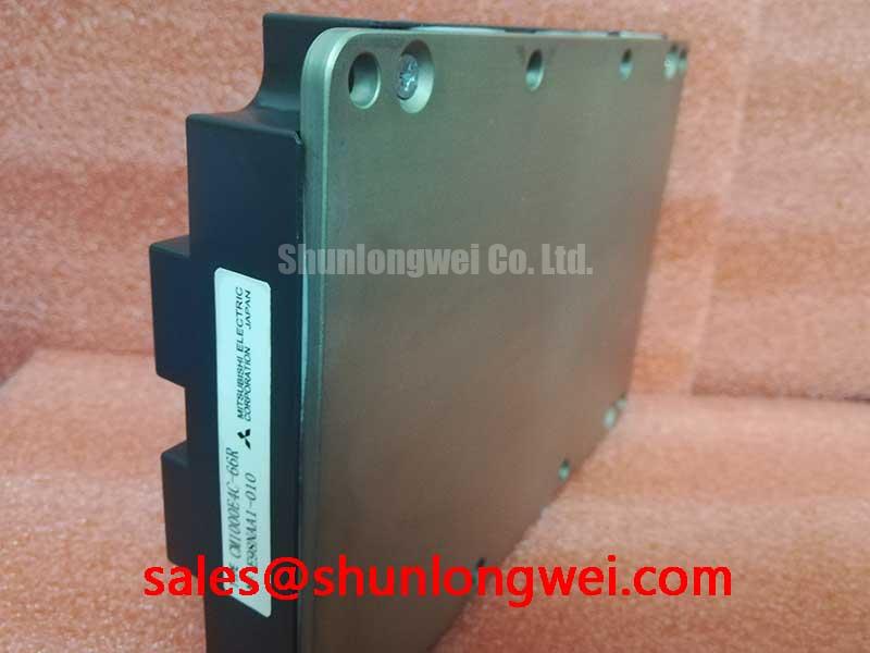
Mitsubishi Electric CM1000E4C-66R 3300V 1000A IGBT Module
Begin a field inspection by isolating the converter, confirming the nameplate voltage boundary, and checking the module terminals for abnormal cold-state impedance before removing the existing power assembly. The CM1000E4C-66R is a Mitsubishi Electric IGBT module with an official rated voltage of 3300.0 V, an official rated current of 1000.0 A, and a Module package classification. These are the verified product parameters supplied for this listing; gate-drive, switching, thermal, insulation, and surge limits must be confirmed against the applicable Mitsubishi Electric documentation for the exact revision and installation conditions.
| Parameter | Official specification |
|---|---|
| Manufacturer | Mitsubishi Electric |
| Part number | CM1000E4C-66R |
| Rated voltage | 3300.0 V |
| Rated current | 1000.0 A |
| Package | Module |
For a utility-scale centralized battery energy storage PCS, this device may be evaluated in the high-power switching stage where the bidirectional converter manages battery charging and discharge paths. Suitability remains system-dependent. The engineer responsible for the PCS should compare the original circuit topology, gate-driver interface, cooling arrangement, protection timing, DC-link operating envelope, and mechanical footprint before approving any replacement.
Transient Dynamics and Desaturation Detection on CM1000E4C-66R
Desaturation protection is a system-level protection function rather than an independently confirmed specification of this product listing. In a practical service inspection, first verify that the driver board detects abnormal collector-emitter behavior during a controlled test and that the fault signal reaches the supervisory controller without excessive delay. Type-I and Type-II short-circuit behavior, short-circuit safe operating area, and any target response below ten microseconds must be taken from the approved gate-driver and module application documentation, then validated on the assembled PCS with a suitable probe arrangement.
The protection path should distinguish a genuine overcurrent event from a false trip caused by common-emitter inductance, probe grounding, driver supply disturbance, or an incorrectly referenced desaturation signal. A useful bench sequence is to check the driver supply under switching conditions, confirm the sensing diode and blanking network, and compare the fault waveform with a known-good phase leg. The oscilloscope connection should minimize loop area and preserve the intended reference point; otherwise, the measured collector-emitter transient may reflect the test setup rather than the power stage.
Two-stage soft turn-off is an engineering recommendation for systems where abrupt gate removal could produce excessive inductive overvoltage. The first controlled reduction can limit the current transition, while a subsequent gate clamp or final turn-off state completes isolation. The actual timing, gate resistance, clamp voltage, and driver current must be selected from the module switching data, gate-driver capability, stray inductance, DC-link voltage, and measured peak margins. Do not treat a generic desaturation timing value as an official rating for this module.
The DC-link protection network also deserves inspection. An MOV may be coordinated with other clamping elements to absorb switching and supply transients, but its clamping voltage, energy capability, aging behavior, and fault coordination must match the PCS bus and applicable safety requirements. Verify the complete network during switching tests rather than assigning the MOV responsibility for every overvoltage event. For a separate IGBT module reference, see the CM100DY-12E, without assuming electrical interchangeability.
Investigating High-Altitude and Cosmic-Ray Reliability Risks
Single-event burnout, terrestrial neutron exposure, and altitude-related reliability require source-specific qualification data. No FIT rate, burnout probability, altitude derating curve, or guaranteed operating limit is established by the verified parameters supplied for this product page. Engineers evaluating installation above approximately 2000 metres should obtain the manufacturer’s applicable reliability guidance and assess the actual DC-bus voltage, switching waveform, cooling conditions, enclosure environment, and local protection strategy.
In field troubleshooting, inspect whether unexplained phase faults occur during high-voltage idle, switching transitions, or battery charge and discharge reversals. Record the DC-link voltage, gate signal, collector-emitter waveform, heat-sink temperature, and fault timing at the same instant. A repeated fault under a particular bus condition may justify a derating review, but it does not by itself identify cosmic radiation or SEB as the cause. The investigation should also exclude insulation contamination, gate-driver instability, excessive overshoot, current-sensor error, and an intermittent mechanical connection.
Thermal interface material and clamping uniformity affect the case temperature used in any reliability assessment. A thin, continuous interface layer is a Design Consideration, while the suitable material, application thickness, surface preparation, and mounting force must be determined from the module mechanical documentation and the selected heat sink. Cross-pattern tightening is commonly used to distribute contact pressure, but the applicable screw size, torque, washer arrangement, and sequence must come from the approved mechanical instructions rather than from a generic module practice.
⚠️ Field Alert: De-energize and verify the DC link is discharged before touching the module terminals, gate wiring, or cooling hardware.
For background on how newer wide-bandgap devices alter switching loss, voltage stress, and design tradeoffs, engineers can consult the Wide Bandgap Revolution technical article. That discussion should not be read as evidence that this silicon IGBT module has the electrical characteristics of a SiC or GaN device.
Thermal and Electrical Optimization During Pulsed Operation
A battery PCS can impose repeated thermal cycling as the converter changes between charge, discharge, standby, and fault-recovery states. The CM1000E4C-66R official current rating is 1000.0 A, but the allowable current in a particular pulse profile depends on switching frequency, duty cycle, junction temperature, case temperature, cooling performance, electrical waveform, and the manufacturer’s safe operating data. The rating should not be converted directly into a universal pulsed-overload or ITSM limit.
For a practical thermal assessment, place temperature measurement where it represents the module case interface and correlate that reading with the electrical loss calculated from the verified conduction and switching data. A multi-RC thermal model can then estimate junction response to a pulse train, but every resistance and time constant must be sourced from the relevant technical documentation or identified through a controlled characterization test. Peak junction temperature should be checked against the documented limit after including the thermal impedance of the interface material, heat sink, coolant path, and enclosure.
When a field unit trips after several charge and discharge cycles, compare the thermal waveform over the complete operating sequence instead of checking only the first pulse. Inspect heat-sink flatness, interface coverage, fan or coolant operation, busbar connection temperature, and phase-current balance. If the measured case temperature rises while electrical current remains similar, the cooling path or mounting interface deserves attention. If the electrical waveform changes first, investigate gate timing, commutation behavior, DC-link ripple, and current measurement before assigning the issue to thermal fatigue.
The MOV network should be reviewed together with the switching loss and thermal model. Repetitive clamping can add heat and may change its electrical behavior over time, while an underspecified network can leave the IGBT exposed to excessive transient voltage. The system designer should verify the energy coordination, clearance, creepage, fault containment, and service replacement procedure for the complete PCS assembly. No independent EMC, safety, insulation, or lifetime certification should be inferred from the module designation alone.
Battery state estimation also influences thermal duty because the PCS control system may alter current commands near charge or discharge limits. General battery state-of-charge concepts can be reviewed through this state-of-charge reference, while the power semiconductor switching and protection principles can be compared with the STPOWER IGBT technical resource. These external references do not replace the Mitsubishi Electric data applicable to this module.
Multi-Module Parallel Current Sharing on CM1000E4C-66R
Parallel operation requires more than matching the printed current rating. Static sharing can be influenced by the positive temperature coefficient of conduction voltage in the operating region, but the actual balance depends on semiconductor characteristics, temperature, busbar resistance, emitter and collector layout, gate-driver matching, and control timing. The CM1000E4C-66R listing does not provide a parallel-operation guarantee, sharing tolerance, or recommended module count, so the system integrator must verify these points from the manufacturer’s application data.
Keep the power paths geometrically symmetrical where modules operate in parallel, and make the gate-drive paths equivalent in impedance and reference arrangement. Minimize parasitic commutation-loop inductance to reduce unequal turn-off overshoot, then verify each module’s collector-emitter waveform with isolated, properly rated measurement equipment. A current imbalance should be investigated through waveform timing, busbar resistance, temperature distribution, driver output, and sensor calibration rather than attributed to one component without evidence.
During a replacement evaluation, compare the mechanical mounting position, terminal orientation, gate connection, isolation requirements, heat-transfer path, and protection interface with the removed unit. A same-family component such as CM50DY-28H may be reviewed as a separate procurement or topology reference, but its voltage, current, package, and switching data must be checked independently before any substitution decision. The original PCS designer remains responsible for confirming electrical and mechanical compatibility.
Before returning equipment to service, perform insulation checks using the procedure and test levels specified for the assembled converter, confirm gate signals at low-energy conditions, and review the first controlled switching waveform for overshoot, ringing, and unequal current rise. The final acceptance decision should be based on documented system measurements against the approved design limits for the particular battery PCS.