Content last revised on September 27, 2026
DS1112SG Operational Boundaries: Check the Diode, Not a Gate Drive
With the equipment isolated and its DC link discharged, compare the cold forward and reverse resistance of the installed DS1112SG against the original maintenance record before disturbing the clamp assembly. An in-circuit reading can include parallel paths, so an unexpected result calls for isolation and a repeat measurement rather than an immediate verdict on the diode.
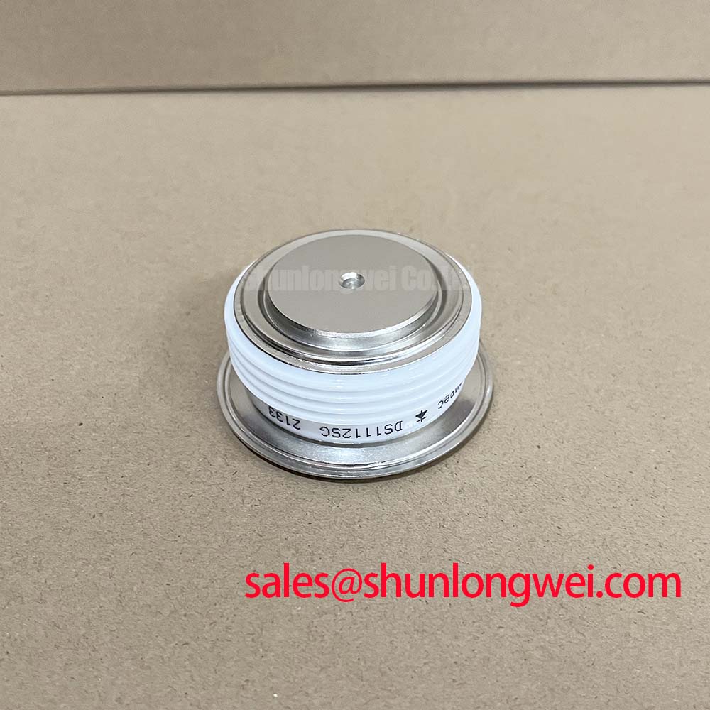
The Dynex DS1112SG is a double-side-cooled disc diode specified for rectification or freewheeling. Its 6000 V repetitive peak reverse voltage and 630 A average forward current are Official Specifications. They describe diode operating boundaries, not a gate-drive supply, galvanic isolation barrier or common-mode transient immunity rating. This device has no gate to trigger; isolation and spurious-trigger checks belong to any associated converter control electronics.
As a Design Consideration, compare the measured reverse-voltage waveform with the diode rating under the equipment’s actual switching conditions. Cable and busbar inductance can raise transient stress above the steady DC-link voltage. High-voltage junction behaviour, including impact ionization, explains why a reverse-voltage rating should not be treated as permission for uncontrolled overvoltage. The system engineer must establish the operating margin by measurement.
Assembly Integrity and Layout: Restore the Disc’s Thermal Path
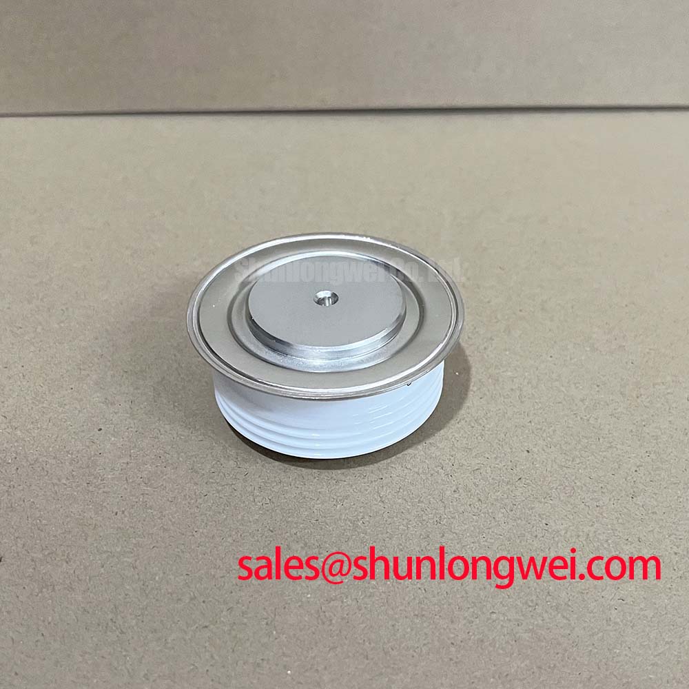
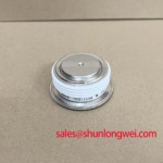
Before removing the failed unit, record its polarity, clamp position, contact orientation and heatsink arrangement. The DS1112SG’s double-side-cooled disc construction makes both external contact faces part of the heat-removal path. Inspect them for contamination or uneven contact, then check that the clamp and cooling hardware match the original assembly documentation. A cold electrical check alone cannot confirm a sound thermal interface.
Field Alert: Discharge the DC link and follow the equipment’s specified clamp-force procedure before loosening or tightening the disc assembly. As a Design Consideration, apply interface material and pressure only as directed by the equipment and device mounting instructions; neither clamp force nor a replacement spring setting can be inferred from the diode’s voltage and current ratings.
Desaturation detection, short-circuit safe operating area and soft turn-off are IGBT protection concepts, not functions inside the DS1112SG. Where an IGBT operates in the same converter, inspect its protection path separately. The linked FZ800R12KS4_B2 is an example of a separate switching component for topology review, not an interchangeable rectifier. For the diode position, coordinate semiconductor fuse protection against the documented fault current and device surge limits; the supplied DS1112SG specifications do not establish a fuse rating or clearing-time guarantee.
Field Diagnostics and Commissioning: Separate Diode Faults from Gate Noise
If a replacement diode tests consistently but the converter still trips, trace the current path on the equipment schematic before changing drive settings. Check the DS1112SG’s installed polarity, inspect adjacent connections, and compare voltage waveforms at equivalent points in a known-good phase where safe measurement access exists. Repeated trips can involve the control board, another semiconductor or the load; they do not identify a single failed part by themselves.
Gate-voltage spikes caused by parasitic capacitance, Miller-clamp behaviour and negative gate bias concern nearby controlled switches. The DS1112SG has no gate terminal, so those measures cannot be applied to it. As a Design Consideration, keep the distinction clear during commissioning: verify diode reverse-voltage stress and cooling at its own terminals and contact faces, while evaluating gate noise at the relevant switch and driver. The Ultimate IGBT Knowledge Base provides background for that separate switching-device assessment.
DC-Link and Braking Checks Around the DS1112SG
When a drive reports a DC-link fault during deceleration, identify whether the DS1112SG sits in a rectification or freewheeling path before attributing the event to it. A braking chopper and its resistor handle regenerative energy only where the equipment topology provides them. The diode’s 6000 V reverse and 630 A average forward ratings do not specify braking energy, chopper capacity or resistor size.
For an electric material-handling or forklift traction repair, treat suitability as an equipment-specific compatibility question, particularly if the original system is described as low voltage. Confirm the original diode part number, circuit position, polarity, mechanical clamping arrangement and cooling scheme against the machine documentation. Check measured current and reverse-voltage stress under representative operation before returning the equipment to service. The DIM800DCM17-A can be examined when reviewing a different power-stage architecture, but its compatibility with a DS1112SG disc position must not be assumed.