Content last revised on October 5, 2026
EVK71-055 Assembly Integrity and Common-Mode Transients
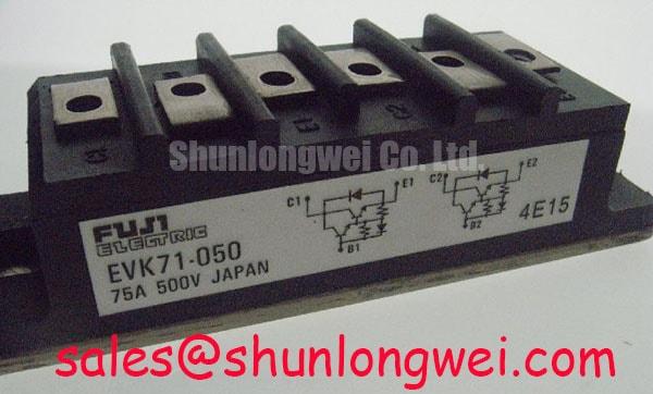
With the DC link discharged and the equipment isolated, check the markings on EVK71-055 against the removed unit, then record cold terminal readings before disturbing the wiring. The supplied product identification describes a Fuji Electric IGBT module in a Fuji Power Module housing with a 75.0 A rated current (Official Specification). “Standard Industrial Rating” is not a numeric voltage specification. Confirm the voltage rating, terminal diagram and applicable test conditions from the original Fuji documentation before deciding whether the module fits a repair.
Start at the mounting surface and terminal connections. Photograph the existing lead positions, look for cracked housing edges or signs of terminal movement, and compare the installed footprint with the replacement before loosening the assembly. A terminal that appears secure can still have a poor electrical connection, so inspect the mating hardware and contact surfaces as well as the fastener heads. The 75.0 A rating identifies a current boundary for the module; it does not establish the current available in a particular inverter without its operating and cooling conditions.
Common-mode transients are a system-level concern whenever a switching node moves rapidly relative to the control electronics. As a Design Consideration, keep driver wiring and its return path close together, maintain the clearances required by the equipment design, and examine where power conductors pass near low-level control wiring. An intermittent trip or unexpected gate activity should prompt a comparison of driver signals and switching waveforms with a known-good channel, using measurement equipment and probing practices appropriate to the circuit voltage.
Do not assign an isolation withstand value or common-mode transient immunity rating to EVK71-055 from its part number. Those limits depend on the documented module and driver specifications, and a driver’s isolation rating is not automatically the rating of the assembled equipment. Fuji Electric’s RC-IGBT module information illustrates a distinct product family; its construction or ratings should not be transferred to this part without an explicit documentation match.
For an electric forklift traction inverter or another material-handling drive, compatibility assessment should begin with the equipment schematic and the removed module’s complete identification. Check the terminal arrangement, driver connections, mechanical envelope and cooling interface before considering the application. The equipment’s bus voltage and switching behavior, rather than the phrase “Standard Industrial Rating,” determine which documented voltage and insulation limits must be verified.
EVK71-055 Mounting Interface and Voltage Margin
Before fitting the module, clean and inspect the heatsink contact area for raised damage, old interface material and unevenness that could prevent consistent contact. Apply thermal interface material according to the equipment or material supplier’s procedure, then tighten the mounting hardware in the specified sequence. An apparent electrical fault can be complicated by poor thermal contact, so record the condition of the removed assembly rather than assuming that a replacement module alone resolves the shutdown.
Field alert: Do not reuse a mounting torque or thermal-paste thickness from another module unless the relevant hardware and installation instructions support it.
Voltage margin also needs an equipment-specific check. As a Design Consideration, compare the documented voltage limit for the exact module with the DC-link level and measured switching peaks under the machine’s relevant operating conditions. Keep the power loop compact where the equipment layout permits, because stray inductance can contribute to turn-off overshoot. The final acceptable margin is a system engineering decision based on the verified module rating, measurement uncertainty and operating envelope; no numeric voltage limit has been established here for EVK71-055.
Altitude and radiation-related reliability cannot be reduced to a field rule for this part. Without a manufacturer qualification document or an applicable reliability analysis, there is no defensible single-event burnout rate, failure-in-time figure or altitude derating value to apply. If the equipment specification calls for operation at an unusual site altitude, request the relevant component and system documentation and assess cooling and voltage stresses together rather than treating either factor in isolation.
A parts comparison is similarly a documentation task, not a nameplate shortcut. The 3MBI50SX-120-02 is a separate module to examine when assessing possible service options; its current rating, voltage rating, topology, terminal map, dimensions and driver requirements must be checked against the original design. It should not be treated as a confirmed drop-in replacement for EVK71-055 on the basis of a catalogue association.
EVK71-055 Waveform Checks with Long Motor Leads
If an inverter trips after motor-cable work, document the cable routing and terminations before changing power hardware. Inspect the motor terminals, shield connections and protective-earth path, then compare fault records with conditions observed during a controlled test. A cold meter check can reveal an obvious short or open connection, but it cannot characterize switching overshoot or high-frequency common-mode current.
As a Design Consideration, long motor leads can introduce reflected-wave behavior when cable impedance and the motor termination interact with the inverter’s switching edges. Bearing-current concerns require separate attention to the motor, cabling, grounding and switching waveform. Neither a terminal-voltage multiplication factor nor a filter size can be assigned to EVK71-055 without the installation details and measured waveforms. Use an appropriately rated differential measurement method to examine voltage at relevant points, and have the system engineer evaluate any output filter or common-mode choke against the drive and motor documentation.
Keep those observations distinct from evidence of module damage. A high motor-terminal peak does not, by itself, identify a failed IGBT, while a repeatable driver fault does not prove that the motor cable is at fault. Compare phase behavior, gate commands and fault timing where safe access permits. The Ultimate IGBT Knowledge Base provides background on switching mechanisms; the equipment schematic and measured signals remain the basis for this repair decision.
Fuji Electric also publishes information on brake chopper IGBT modules. That category is useful when identifying a braking subsystem during schematic review, but it does not establish the internal circuit or intended application of EVK71-055. Trace the installed terminals to the actual power circuit before using a product-family description to interpret a waveform.
EVK71-055 Gate-Loop Layout and Benchtop Diagnosis
At the bench, preserve the original driver harness identification and map each connection against the equipment drawing before reconnecting the module. Inspect plug seating, conductor strain and the routing of gate wiring beside high-current conductors. With power removed, compare cold readings across corresponding circuit paths only when the surrounding circuit makes that comparison meaningful; connected snubbers, drivers and parallel components can alter meter results.
During an authorized powered test, examine the gate signal at the accessible points specified by the service procedure and compare it with the corresponding healthy channel. As a Design Consideration, minimizing the area of a gate-drive loop can reduce susceptibility to noise coupled from the power path. If the documented module and driver arrangement provides a dedicated emitter-sense connection, follow that documented return path rather than assuming such a terminal exists on EVK71-055. The terminal diagram must settle that question before wiring changes are made.
Oscillation, a gate-driver alarm and an abnormal switching edge deserve coordinated checks rather than a single-cause diagnosis. Verify the driver supply and command state, inspect the return connection, and correlate the gate waveform with the power waveform under controlled conditions. If the signals differ from a known-good channel, stop before increasing load and resolve the discrepancy using the circuit documentation. Record the module marking, measured observations and any changes to wiring or mounting so the next technician can distinguish an installation issue from a recurring system fault.