

Content last revised on November 1, 2026
FF400R16KF4 Operational Boundaries: Fuse Coordination and Module Protection
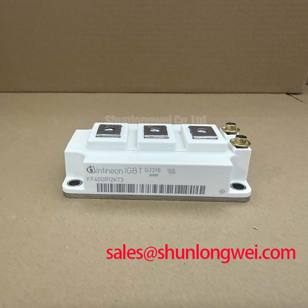
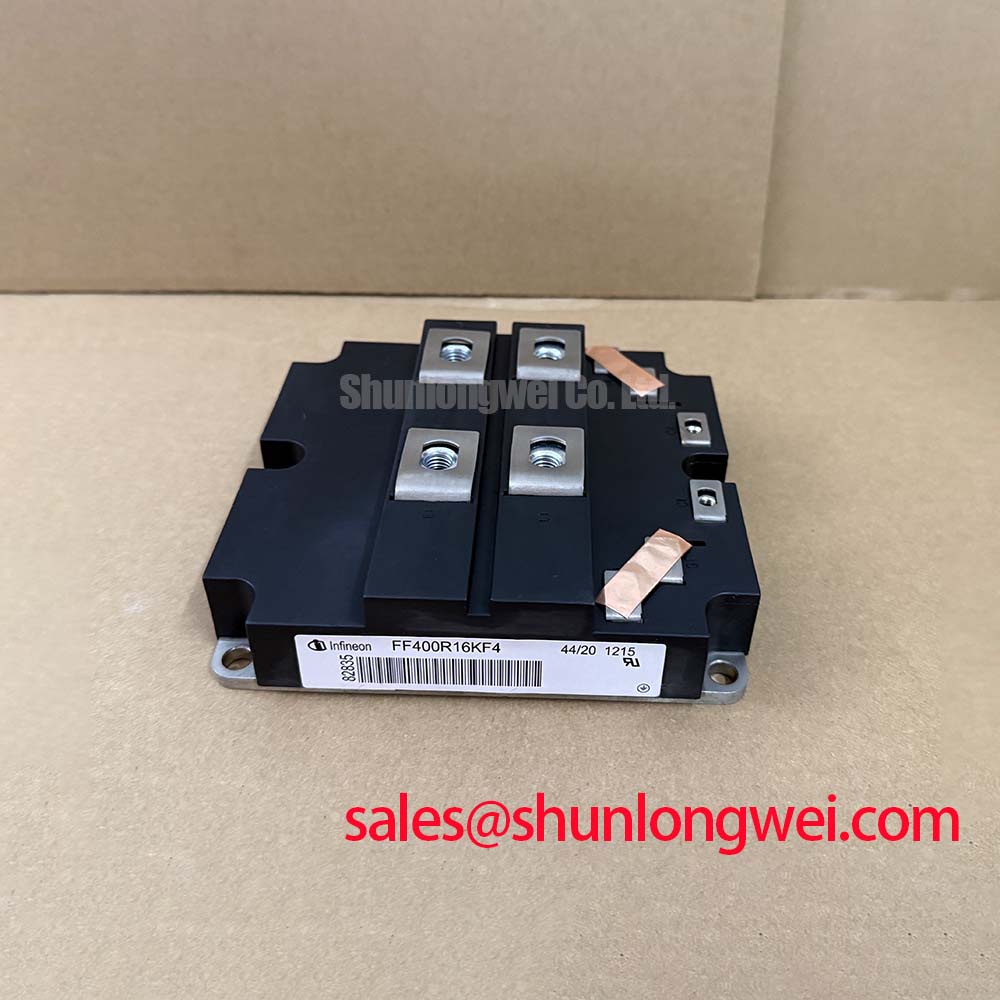
Isolate the DC link, verify discharge, and compare the removed module’s identification with the converter schematic before reconnecting its power terminals. The Infineon FF400R16KF4 has a 1600 V collector-emitter voltage rating and a 400 A DC collector-current rating at a case temperature of 80°C (Official Specification). Preserve that temperature condition when assessing the replacement against the equipment’s operating load.
The module uses a 62 mm dual package, with 800 A repetitive peak collector current and 0.038 K/W junction-to-case thermal resistance per IGBT (Official Specification). Its 4.0 kV RMS isolation test rating at 50 Hz for 1 minute is also an Official Specification, not an instruction to repeat that test on an assembled converter. These electrical and physical boundaries provide the starting point for protection, cooling, and interface checks.
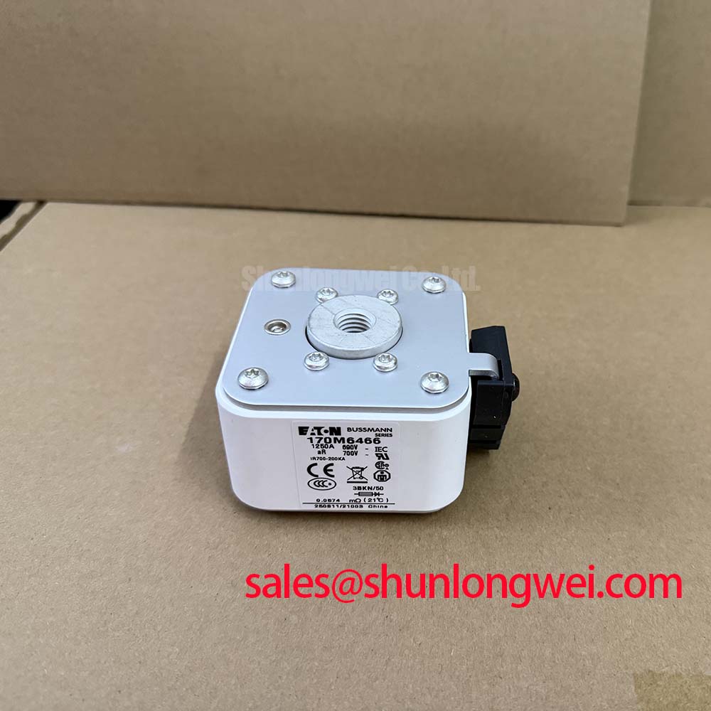
Compare the semiconductor fuse’s total clearing characteristics with the fault current available from both the supply and the charged DC-link capacitors. As a Design Consideration, fuse coordination should account for circuit voltage, prospective current, interruption behavior, and energy delivered before clearing. A fuse’s I²t value alone does not establish that an IGBT module will survive a short circuit or that its housing will remain intact.
Type-2 coordination terminology should not be treated as an intrinsic FF400R16KF4 performance claim. Where an equipment specification requires a particular coordination category, the assessment belongs to the complete protective arrangement and its applicable test requirements. Likewise, the 800 A repetitive peak rating is not a short-circuit withstand rating, and an IGBT current rating cannot be substituted for a diode surge-current limit.
Engineering Recommendation: examine the gate-driver fault record alongside the fuse condition. Desaturation detection monitors abnormal collector-emitter behavior during commanded conduction; its blanking interval, detection threshold, propagation delay, and controlled turn-off response must work together. Excessively abrupt fault turn-off can increase inductive overvoltage, while delayed interruption can increase semiconductor heating. Establish the protection sequence against the device’s applicable short-circuit safe-operating-area conditions rather than inferring it from normal saturation behavior.
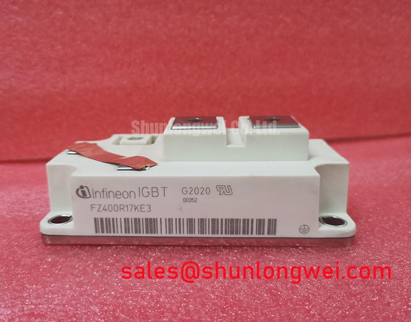
Replacement assessment also requires a topology check. The FS400R07A1E3 should be evaluated as a separate device, not presented as a verified direct replacement for the FF400R16KF4. Compare voltage class, circuit configuration, terminal assignments, mechanical drawing, and driver requirements before considering any substitution. Matching a headline current figure does not establish interchangeability.
Inspect the fault-current path for displaced conductors, damaged barriers, and conductive debris before restoring power. Clearance and creepage decisions should follow the converter’s insulation coordination, working voltage, environment, and applicable equipment requirements. Increasing fuse speed cannot compensate for a compromised physical separation between live conductors and the grounded enclosure.
Benchtop Waveform Tuning: Planar Symmetrical Busbar Geometry for the FF400R16KF4
Capture collector-emitter voltage and collector current during controlled switching tests, using probes and connections suitable for the measurement environment. Design Consideration: turn-off voltage includes the DC-link contribution and the additional voltage produced by commutation-loop inductance during current change. Reduce the enclosed loop area and keep outgoing and return conductors closely coupled where insulation and mechanical requirements permit.
Pro Tip: Favor balanced planar busbar paths to reduce unequal commutation inductance, then validate turn-off voltage margin with controlled double-pulse measurements. The acceptable geometry is determined by measured switching behavior, insulation constraints, terminal loading, and assembly tolerances, rather than an arbitrary universal inductance target.
Engineering Recommendation: assess snubber placement before selecting capacitance or resistance. A suppression network connected through a long path can leave substantial local overshoot at the module terminals. Component selection should consider measured ringing, repetitive energy, capacitor pulse capability, resistor dissipation, and the effect on switching losses. DC-link ripple smoothing is a separate task: bulk capacitance supporting lower-frequency energy variation does not automatically suppress a fast commutation transient.
Check gate-emitter behavior at the module interface when investigating unwanted turn-on. Collector voltage transitions can couple current through the gate-collector capacitance, making driver sink capability and return-path impedance important. Driver isolation also deserves attention: optocoupler or digital-isolator common-mode transient immunity should be evaluated against the actual switching environment. Gate resistance and any active clamping arrangement remain system-selected measures, validated for both switching stress and loss.
In a larger converter architecture, a module such as the FF1000R17IE4 belongs in a separate stage-level assessment; it is not automatically an upstream rectifier or a required companion. If the equipment includes a phase-controlled rectifier, its thyristor triggering and line-frequency conduction control remain distinct from the FF400R16KF4 gate-drive requirements. Keeping these functions separate makes waveform diagnosis more useful.
The Infineon article on enhanced module design and IGBT5 performance provides context for the relationship between packaging and switching behavior. It should not be used to assign IGBT5 or TRENCHSTOP technology to this model. Device-family comparisons can instead begin with the Infineon IGBT Modules Overview.
FF400R16KF4 Insulation Testing and Thermal Assessment
Disconnect sensitive control circuitry and define the test connections before applying an insulation tester between the power circuit and baseplate. Design Consideration: an assembled converter can contain suppression components, sensing circuits, and other connected paths that affect readings or experience unintended test stress. Use the equipment manufacturer’s service procedure to determine which connections are isolated and how the assembly is discharged afterward.
The 4.0 kV RMS, 50 Hz, 1-minute isolation test specification does not establish a DC megohmmeter acceptance threshold. An AC withstand test and a DC insulation-resistance measurement evaluate different aspects of insulation behavior. Record the test method, environmental conditions, and connection arrangement so that readings can be compared meaningfully; do not interpret one resistance measurement as proof of an internal substrate’s condition.
Engineering Recommendation: examine accessible insulating surfaces for contamination, tracking, and damage, then clean them using an equipment-approved process. Dust and moisture can affect surface leakage, but an abnormal reading does not identify a single cause. Distinguish external contamination from connected-circuit effects before deciding whether the module or another assembly requires further investigation.
Thermal assessment should start with the case-to-cooler interface. Check contact surfaces, mounting flatness, fastener procedure, and the specified interface material without imposing generic torque or layer-thickness values. The 0.038 K/W per-IGBT junction-to-case rating describes only part of the heat path. Pulse-temperature assessment requires the applicable transient thermal-impedance characteristics and actual loss history, rather than applying steady-state thermal resistance to every switching event.
For repeated loading or bidirectional power operation, designers should evaluate heating and cooling excursions across the mission profile. The Industrial Applications resource offers broader application context, but does not establish a model-specific lifetime prediction or qualification result. Keep service decisions tied to measured thermal behavior and the equipment’s documented acceptance criteria.
Preventing Spurious Faults: Long Motor Lead Reflected Wave Voltage Guidelines for FF400R16KF4
Measure the inverter output and motor-terminal waveform separately when investigating trips associated with a long motor cable. Design Consideration: cable propagation and impedance mismatch can produce motor-terminal reflections that differ substantially from the voltage observed at the inverter. Their magnitude depends on switching-edge behavior, cable construction, length, termination, and motor impedance; a fixed voltage multiplier is not a universal diagnostic limit.
Engineering Recommendation: select any output reactor or dv/dt filter against the complete drive-cable-motor combination. Assess voltage stress, filter heating, resonance, output-frequency range, and interaction with current control. A network intended to moderate motor-terminal edges does not replace local DC-link commutation control, and changing an output filter can alter the waveforms used by protection and feedback circuits.
For potential high-speed rail or heavy-freight locomotive traction-inverter integration, equipment engineers should verify the complete electrical, mechanical, cooling, environmental, and qualification requirements before accepting the FF400R16KF4. Its stated ratings alone do not establish railway suitability. During fault investigation, correlate trip timestamps with phase current, DC-link voltage, gate-driver status, and motor-terminal measurements to distinguish reflected-wave stress from sensing interference or genuine overcurrent.
After a cable-routing or filter change, repeat the affected operating checks under the equipment’s controlled commissioning procedure. Retain comparable probe positions and operating conditions so that reduced ringing is not confused with a measurement change, and verify that any improvement at the motor terminals has not introduced excessive module switching stress or filter temperature rise.