

Content last revised on October 10, 2026
Preventing Spurious Faults: Power-Up Shoot-Through Guidelines for FP10R12YT3
With the drive isolated and its DC link verified discharged, inspect the gate-driver connections and power-terminal seating before investigating a startup overcurrent trip around the FP10R12YT3. Loose connections, unstable driver power, and switching commands arriving during initialization deserve separate checks; a fault message alone does not identify a failed semiconductor.
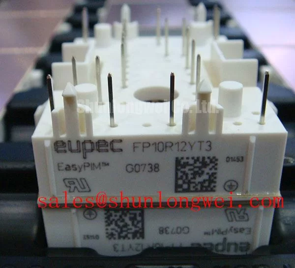
The Infineon FP10R12YT3 is an IGBT Module with a 1200 V voltage rating, a 10 A current rating, and a Module package designation, identified here as Official Specification. For replacement planning, match the complete part designation, terminal arrangement, mounting interface, and circuit connections. These checks establish whether the component fits the existing assembly before commissioning changes are considered.
Preventing Spurious Faults: Power-Up Shoot-Through Guidelines for FP10R12YT3
Trace the auxiliary driver supply, undervoltage lockout, and PWM enable signals together to establish whether the gates remain controlled throughout startup. As a Design Consideration, the controller should withhold switching commands until the driver supplies and protection circuits have reached their validated operating states. Investigate shutdown sequencing as well: removing driver power while the DC link remains energized can leave the gate-control path in an unintended condition.
Measure gate-to-emitter behavior at the module connection rather than relying exclusively on a controller test point. The signal at the controller can appear orderly while the local gate reference moves during switching. Use appropriately rated differential or isolated measurement equipment, and arrange the probes so their connections do not introduce a misleading pickup loop. Compare the enable transition with the actual gate waveform and the driver fault output.
Negative gate bias, where supported by the selected driver and module limits, is a Design Consideration for resisting unwanted turn-on during rapid voltage transitions. It is not a substitute for a controlled startup state, adequate gate discharge, or validated interlocking. The off-state bias belongs to the complete driver design; it should not be assigned from a generic voltage range. Infineon’s EiceDRIVER™ gate-driver IC information provides relevant context for assessing isolation, undervoltage behavior, and protection functions in compatible driver circuits.
Inspect the routing between each gate output and its corresponding emitter reference. Keep the gate-control loop separated from high-current commutation paths where the assembly permits, and avoid shared connections that allow power-current voltage drops to disturb the driver reference. Clearance decisions depend on the equipment’s insulation requirements, conductor geometry, and environmental conditions; the module’s voltage rating is not a prescribed PCB spacing.
When evaluating compatibility with a compact industrial inverter or high-speed CNC spindle drive, compare the existing startup sequence, PWM interlocks, and protection interface with the proposed installation. A procurement comparison involving BSM300GB120DLC should remain a separate topology and mechanical assessment, not a presumed direct substitution. Sharing a product category does not establish matching terminal functions, driver requirements, or mounting geometry.
For intermittent startup trips, capture the auxiliary supply through both energization and shutdown rather than checking only its steady-state value. Correlate any supply disturbance with the gate waveform and fault latch. This separates a sequencing issue from other possibilities without turning one symptom into a definitive diagnosis.
Field Diagnostics & Commissioning: Oscilloscope Waveform Verification in FP10R12YT3 Topologies
Compare turn-on and turn-off waveforms at the FP10R12YT3 terminals before changing external gate resistors on a legacy driver board. As an Engineering Recommendation, record the installed resistor arrangement and distinguish the charging and discharging paths where separate paths exist. Adjustments should address observed switching behavior rather than assume that a faster transition improves the repaired equipment.
A lower gate-path impedance can accelerate switching but can also increase ringing and transient stress. A higher impedance can moderate transitions while increasing switching dissipation. Evaluate the resulting collector-emitter waveform, gate waveform, and current behavior together under a controlled commissioning procedure. Resistor selection should follow the driver’s output capability, the module’s switching characteristics, and the equipment’s measured response, with the final values established by the responsible system engineer.
Check complementary gate signals for effective non-overlap at the power-stage connections. Controller dead time does not, by itself, describe the interval between actual device transitions: propagation delays, gate discharge, and operating conditions also contribute. As a Design Consideration, assess both unwanted overlap and excessive non-overlap, since the latter can affect waveform quality and diode conduction. Retain the equipment’s validated timing unless testing supports a documented change.
For desaturation protection, inspect the collector-voltage sensing path, blanking behavior, fault propagation, and gate shutdown response as one chain. Desaturation detection observes collector-emitter voltage while the IGBT is commanded on; it is not equivalent to applying a static saturation-voltage threshold without considering switching transients. The protection response must be coordinated with the applicable device short-circuit limits and driver documentation, rather than assigned an unsupported universal detection time.
Two-stage soft turn-off is a Design Consideration where the driver supports it. Controlled gate discharge can reduce the abrupt current change that contributes to turn-off overshoot, but an overly slow shutdown can increase fault energy. Verify the implemented sequence using the equipment’s approved protection test method. Intentional short-circuit testing is not an appropriate improvised maintenance check.
Read the power-stage schematic before associating a related module with a rectifier, inverter, or auxiliary role. The FS100R12KT4G_B11 can be considered separately during topology comparisons, but its place in a circuit must follow its own documented connections and ratings. A related product link does not establish an upstream rectifier function or compatibility with FP10R12YT3 wiring.
During deceleration, include DC-link behavior in the waveform review. If the equipment uses a braking chopper and resistor, verify the command path, resistor continuity, cooling condition, and thermal protection against the original equipment requirements. Regenerated energy handling belongs to that braking assembly, not to the IGBT voltage rating alone. The Industrial Applications reference offers broader application context; equipment documentation remains the basis for acceptance limits.
Assembly Integrity & Layout Architecture: Screening Ceramic DBC Substrate for Micro-Cracks in FP10R12YT3
Separate the semiconductor assembly from connected electronics before any approved insulation test, and identify the permitted test points from the module and equipment documentation. As a Design Consideration, an insulation measurement can reveal an abnormal leakage path, but it cannot identify an internal ceramic crack by itself. Neither a universal test voltage nor a resistance acceptance threshold should be imposed on FP10R12YT3 without an applicable manufacturer procedure.
Inspect accessible insulating surfaces for conductive dust, moisture tracks, damaged barriers, and contamination around terminals. Cleaning should preserve the housing and insulation surfaces, using the equipment’s approved materials and drying method. Measure accessible spacing against the assembly drawing rather than estimating it visually. Creepage follows the insulating surface, while clearance concerns the shortest air path; contamination and displaced wiring can affect these paths differently.
After movement between cold and warm areas, check for condensation before energization. As an Engineering Recommendation, maintenance scheduling should account for cabinet contamination, cooling performance, and environmental exposure rather than assume a fixed interval applies to every installation. Repeated leakage changes should be investigated alongside humidity and surface condition, without assigning a single internal failure mechanism.
Inspect the mounting surface and thermal interface whenever the module is removed. Retain the approved interface material and application method, checking for uneven contact, displaced material, and mechanical damage. Film thickness and fastening torque belong to the applicable assembly instructions, not to generic workshop values. Do not infer a pressure-contact structure, disc-spring arrangement, or double-sided cooling requirement from the package designation.
Maintenance Note: Regularly trend terminal temperature rise and verify cooling airflow before treating an increasing module temperature as evidence of semiconductor deterioration.
Use the specified fastening method and a calibrated tool when restoring terminal and mounting connections. Record disturbed joints, inspect the fan and heatsink passages, and compare temperatures under repeatable operating conditions. If heating remains localized, investigate the associated connection and measurement conditions; if it follows reduced airflow or broad heatsink warming, examine the cooling path before returning the equipment to service.