

Content last revised on October 14, 2026
PM10CZF120 Circuit Protection & Reliability: Calibrating Mechanical Attachment to Prevent Connection Stress
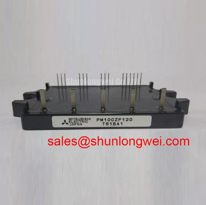
I check whether the external power connections pull against the module before tightening any equipment-side terminal hardware. With the assembly isolated and the DC link safely discharged, cable stiffness, bracket alignment, and mounting flatness deserve attention before electrical testing. A connection that reaches its fixing point only under force can transfer that load into the module interface. For the PM10CZF120, the practical objective is to support the external conductors without treating the package as a structural anchor.
Design Consideration: Where the equipment uses threaded power connections, compare screw engagement, washer arrangement, and available clearance with the assembly drawing. A screw bottoming in a blind hole can feel tight without producing the intended clamping force. An unsuitable washer stack can also change engagement or concentrate pressure. These checks concern the actual connection hardware; they do not establish that this module has threaded power terminals or a particular internal busbar construction.
Inspect the installed interface for tilted connectors, displaced supports, damaged insulation, and evidence that conductors move when adjacent fasteners are loosened. Remove externally imposed strain before restoring the connection. If the board or connector carries the module connections, assess its supports and alignment instead of applying rules intended for bolted busbars. Mounting torque, fastening sequence, and permitted mechanical loading should follow the applicable component and equipment instructions, not a generic screw-size assumption.
The PM10CZF120 product reference identifies a Mitsubishi Electric IPM rated at 1200 V and 10 A. These are Official Specification values, not an equipment operating prescription. During replacement assessment, match the complete model designation, connection arrangement, control-board interface, mounting envelope, and cooling arrangement. A mechanically convenient installation is not sufficient if the drive board expects different input logic or protection behavior.
Design Consideration: Vibration and thermal expansion make conductor support especially important at transitions between rigid and flexible parts. Arrange the external connection so that expansion does not repeatedly lever against the package or circuit board. Where movement is suspected, inspect support positions and compare the assembly before and after a controlled thermal run. A visible housing defect or unstable connection warrants investigation, but neither observation alone identifies an internal fracture mechanism.
Cooling maintenance belongs in the same inspection because blocked airflow changes the temperature excursion experienced by the complete assembly. Check heatsink fins, fan operation, inlet restrictions, and contamination around the module mounting area. Assess thermal-interface condition when the assembly is opened under the approved service procedure, rather than assigning an unsupported replacement interval. Compare temperature trends at similar load and ambient conditions so that changes in production duty do not masquerade as cooling deterioration.
Maintenance Note: Track connection temperature trends and verify that the heatsink airflow path remains clear during scheduled inspections.
Engineering Recommendation: In cabinets exposed to temperature changes, inspect for condensation before re-energizing and address moisture entry through the equipment enclosure. Keep cleaning methods compatible with the assembly materials and avoid leaving conductive residue around control connections. Maintenance records should capture connection condition, cooling condition, and operating circumstances together. This makes a later temperature increase easier to investigate without attributing every abnormal reading to the IPM itself.
PM10CZF120 Circuit Protection & Reliability: Calibrating Short-Circuit Energy Let-Through Matching
Compare the protective device’s total clearing behavior with the complete fault path before accepting a fuse substitution. The 10 A module rating does not establish the required fuse rating, and a fuse’s current label does not describe how quickly it interrupts a DC-link fault. The assessment should include the prospective fault current, circuit voltage, available stored energy, protective-device interrupting capability, and the equipment’s electronic shutdown sequence.
Design Consideration: Fuse coordination involves the time integral of current squared, commonly written as I²t, but a numerical comparison is valid only when the compared limits describe compatible conditions. A semiconductor short-circuit withstand time under specified gate-drive conditions is not automatically a fuse-compatible I²t rating. Total clearing includes more than the interval before the fuse element melts. Use the protective-device manufacturer’s applicable curves and the module’s specified fault limits to establish the protection strategy.
Separate rapid electronic fault response from upstream fault isolation. The electronic response can reduce the duration of semiconductor conduction, while the fuse or other protective device addresses faults that persist in the power circuit. Stored DC-link energy can remain relevant even after the supply is interrupted. Coordination should therefore examine where the fault current flows and which energy sources remain connected, rather than assuming that one protective element guarantees prevention of package rupture.
During a controlled diagnostic run, examine the relationship between the detected fault, the controller response, and removal of switching commands. Instrument selection and probing must suit the circuit voltage and transient environment. Unexpected shutdown can originate in the power stage, control supply, sensing path, or wiring; the timing record helps distinguish these possibilities. Any claimed response threshold or delay for the PM10CZF120 must come from its applicable documentation rather than from another IPM family.
Design Consideration: Reduce commutation-loop area and unnecessary separation between outgoing and returning current paths to limit turn-off overshoot. A compact or laminated bus arrangement is useful only when its insulation, connections, and placement suit the equipment. The system engineer should validate switching peaks across relevant load and supply conditions. Do not assign a universal parasitic-inductance target or assume that changing the bus arrangement alone resolves the transient.
RC snubbers require the same conditional approach. Their placement, damping action, pulse loading, and heat dissipation depend on the measured ringing and circuit impedance. An arbitrary capacitor or resistor can shift the transient while adding losses elsewhere. Line-frequency ripple should be assessed separately from switching ringing: if the upstream supply uses phase-angle conduction control, its conduction intervals influence charging pulses and DC-link ripple. That behavior belongs to the supply topology, not to an assumed feature of this IPM.
When reviewing the surrounding power stage, the CM35MX-24A is a separate component reference for topology comparison, not an assumed rectifier companion or interchangeable PM10CZF120 replacement. Establish each device’s function from the circuit diagram before comparing its electrical boundaries. This avoids selecting a part by voltage class while overlooking the switching arrangement, drive requirements, or protection responsibilities.
Manufacturer terminology and device documentation can be consulted through Mitsubishi Electric Global Semiconductor Device Technologies. That reference supports checking the relevant product documentation; it does not establish an unlisted fault-energy capability. Keep the service decision tied to the identified module revision, the actual protection circuit, and the equipment’s approved fault-test procedure.
PM10CZF120 Operational Boundaries: Evaluating Output Sinusoidal Filter vs dv/dt Reactor Limits
Measure the switching waveform at the motor connection as well as at the inverter output when a long cable is part of the installation. A satisfactory trace near the PM10CZF120 does not establish the peak voltage reaching the motor. Cable impedance, termination conditions, and switching-edge speed influence reflected-wave behavior. Use appropriately rated differential measurement equipment and a probing arrangement that does not introduce misleading ringing.
Design Consideration: An idealized open-ended transmission line can produce a reflected terminal voltage approaching twice the incident step amplitude. This is a general reflection limit under specific conditions, not a guaranteed motor-terminal voltage or an official PM10CZF120 characteristic. Real installations include motor impedance, cable losses, repeated reflections, and pulse timing effects. Filter selection should follow measured behavior and the motor’s permitted electrical stress, rather than a blanket doubling assumption.
A dv/dt output filter primarily addresses voltage-edge behavior, while a sinusoidal filter aims to attenuate switching-frequency content more extensively. The choice affects inverter loading, voltage drop, filter heating, and control response. Designers should evaluate the filter with the actual switching strategy, cable installation, and motor operating range. A reactor alone should not be treated as functionally identical to a complete dv/dt filter, and neither option has a universal component value suitable for every drive.
Engineering Recommendation: For compatibility assessment in light industrial automation or a multi-joint robotic articulator drive, compare the existing inverter architecture, control interface, cooling capacity, and motor-cable arrangement before considering this module. Positioning accuracy or motion duty does not establish IPM compatibility. Review acceleration, braking, and repeated load transitions using the equipment’s operating profile, then evaluate whether the power stage and selected output network remain within their documented boundaries.
The PM150CSE060 can serve as a separate family comparison reference, but it should not be described as a same-specification substitute for the PM10CZF120. Shared manufacturer branding and the IPM category do not establish matching voltage, current, package, or control characteristics. A replacement comparison should identify those differences explicitly before considering any board, cooling, or protection changes.
Design Consideration: Diode reverse-recovery behavior can contribute to commutation current and switching noise, but no recovery-softness factor is established here for this model. Investigate waveform shape and layout together instead of assigning a generic softness value to the installed module. Likewise, a positive temperature coefficient cannot by itself justify paralleling complete IPMs. Static current sharing, switching timing, connection impedance, and thermal balance require a supported design and system-level validation.
The Resonant Topologies in Home Appliances article offers background on how switching topology changes device stress and test conditions; it is not a PM10CZF120 qualification report or a motor-filter sizing guide. For standards and testing context, consult the VDE Association for Electrical, Electronic & Information Technologies. Component selection does not independently establish equipment EMC compliance, insulation qualification, or operating life.
After an output-filter change, repeat the relevant waveform and thermal checks with the final cable routing and enclosure arrangement. Record the measurement locations, supply condition, load condition, and filter configuration so that subsequent maintenance compares like with like. If motor-terminal peaks improve while module heating increases, investigate the changed inverter loading before approving continued operation. Resolve the measured trade-off through the equipment’s acceptance criteria rather than treating suppression of one waveform feature as complete validation.