
Content last revised on September 10, 2026
Infineon FP10R12NT3 1200V 10A IGBT Module: High-Efficiency Power Switch for Industrial Drives
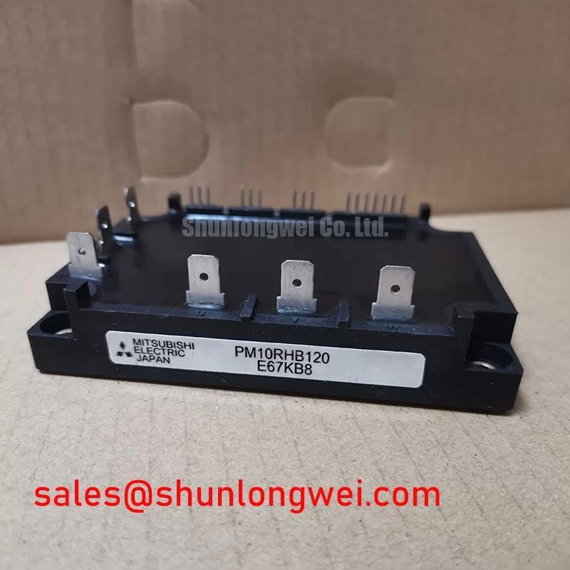
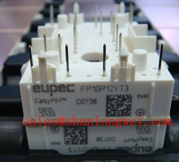
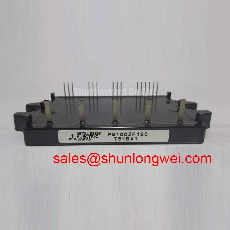
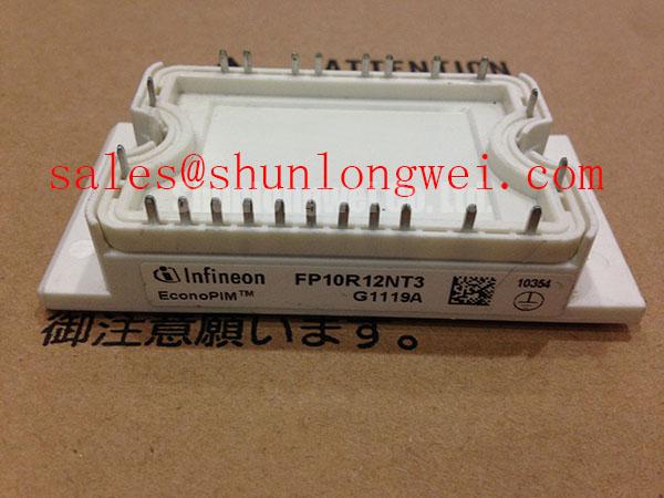
The Infineon FP10R12NT3 is a high-performance 1200V, 10A PIM (Power Integrated Module) designed to optimize power conversion efficiency in low-power industrial inverter setups. Combining a three-phase diode rectifier bridge, a three-phase inverter bridge, a brake chopper, and a temperature-sensing NTC within a single compact housing, this module simplifies complex drive architectures. Its trench-fieldstop IGBT3 technology achieves low conduction losses and high thermal robustness, making it suitable for modern compact motor control systems. For low-power industrial motor drives prioritizing optimized space and efficiency, this 1200V 10A IGBT module represents a highly reliable selection.
Key Parameter Overview
Highlighting Key Metrics for Enhanced Conversion Efficiency
Below is a summary of the primary electrical and thermal ratings for the FP10R12NT3 module as specified in the official technical documentation. These ratings provide a baseline for system-level design calculations.
| Parameter Description | Technical Symbol | Rating Value | Conditions / Notes |
|---|---|---|---|
| Collector-Emitter Voltage | VCES | 1200 V | Tvj = 25°C |
| Continuous DC Collector Current | IC nom | 10 A | TC = 80°C, Tvj = 150°C |
| Repetitive Peak Collector Current | ICRM | 20 A | tp = 1 ms |
| Collector-Emitter Saturation Voltage | VCE(sat) | 1.90 V (Typ) / 2.45 V (Max) | IC = 10 A, VGE = 15 V, Tvj = 25°C |
| Total Power Dissipation | Ptot | 83.5 W | Per IGBT, TC = 25°C, Tvj = 150°C |
| Thermal Resistance (Junction-to-Case) | RthJC | 1.50 K/W | Per IGBT block |
| Integrated Diode Forward Voltage | VF | 1.65 V (Typ) | IF = 10 A, VGE = 0 V |
Download the FP10R12NT3 datasheet for detailed specifications and performance curves.
Application Scenarios & Value
Achieving System-Level Efficiency in Low-to-Medium Power Inverters
The highly integrated architecture of the FP10R12NT3 makes it particularly well-suited for low-power motor control environments. System designers commonly implement this module in low-power servo drives, compact variable frequency drives (VFDs), and auxiliary inverters. By integrating the rectifier, brake chopper, and inverter stages, the module reduces stray inductance and minimizes PCB footprints, accelerating integration into space-constrained industrial automation systems.
When selecting components using a power semiconductor selection guide, engineers evaluate the system's thermal and current headroom. For designs that demand similar compact topologies but require higher current handling, the related FP15R12YT3 offers an output capability of 15A. For even larger industrial applications with heavier motor loads, the FP25R12KE3 provides a 25A rating. This tiered availability enables design flexibility while maintaining consistency in system layouts.
Technical Deep Dive
Evaluating Trenchstop Technology and Switching Loss Profiles
At the core of the FP10R12NT3 is the Infineon Trenchstop IGBT3 technology, which optimizes the trade-off between switching speed and conduction losses. During high-frequency switching, conduction losses are dictated primarily by the collector-emitter saturation voltage (VCE(sat)). What is the primary benefit of the trenchstop technology in this module? It significantly reduces switching and conduction losses. This behavior can be compared to the pressure drop across a water valve: just as a wider valve allows fluid to flow with minimal resistance, a low typical VCE(sat) of 1.90V minimizes electrical friction during the IGBT's conductive state, minimizing efficiency drop-offs.
Furthermore, managing the heat dissipated during continuous operation is critical to preventing thermal degradation. How does the integrated NTC thermistor assist the system? It provides real-time temperature monitoring to prevent thermal runaway. This thermal path is governed by the junction-to-case thermal resistance (RthJC) of 1.50 K/W. This parameter acts like the width of a highway for heat: a lower thermal resistance ensures a wider channel for heat to escape from the silicon chip to the baseplate and eventually to the external heatsink. By maintaining low thermal resistance, the module operates safely within its maximum operating temperature, contributing to long-term reliability in industrial environments. For further details on packaging technologies, review our in-depth analysis of IGBT modules.
The design shift toward modular factory automation has increased the demand for compact, multi-functional IGBT Modules. The integration of auxiliary and primary functions on a single substrate aligns with modern industrial requirements for reduced weight, high reliability, and simplified supply chains.
Frequently Asked Questions
Addressing Key Technical Inquiries for Design Engineers
How does the VCE(sat) of 1.90V impact the overall efficiency of an inverter design?
A low VCE(sat) directly reduces conduction losses when the IGBT is fully turned on. In typical 1200V systems running continuously, this lower saturation voltage ensures that conduction losses remain minimal, which reduces heatsink requirements and allows for more compact drive designs.
What are the mechanical and electrical advantages of the integrated NTC temperature sensor in the FP10R12NT3?
The built-in NTC thermistor measures the module's internal substrate temperature directly. This eliminates the need for external probes, saving board space and providing fast, accurate thermal feedback to the gate drive system to trigger over-temperature protection before damage occurs.
How does the 1.50 K/W junction-to-case thermal resistance (RthJC) affect heatsink selection?
An RthJC of 1.50 K/W dictates how fast heat is transferred away from the junction. Designers must select a heatsink that, when paired with thermal interface material (TIM), maintains the junction temperature below the maximum operating limit of 150°C under worst-case load conditions.
Can the diode forward current rating of 10A handle transient regenerative braking currents?
Yes, the integrated diode is rated for a repetitive peak forward current (IFRM) of 20A (pulse duration of 1 ms). For transient regenerative energy spikes, the diode's I2t rating of 20 A2s provides a robust threshold to prevent forward recovery failures.