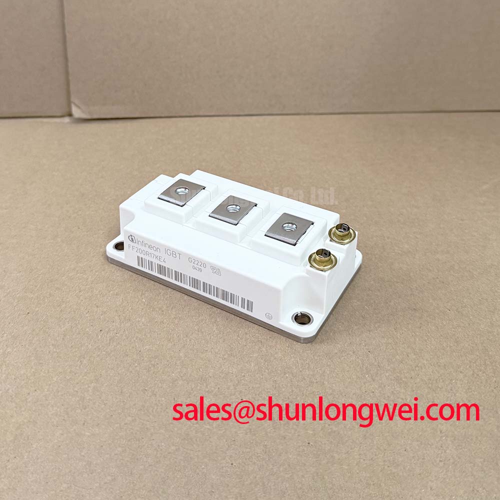


Content last revised on November 1, 2026
Field Diagnostics & Commissioning: Gate Driver Auxiliary Power Sequencing in FF200R17KE4 Topologies
I check auxiliary supply startup and gate-driver fault outputs with the high-voltage supply isolated, then verify that the controller cannot enable switching while a driver remains undervoltage. As a Design Consideration, the intended off-state gate bias should be established before DC-link energization and maintained through the controlled shutdown sequence. Its magnitude belongs to the approved driver design, not a universal commissioning prescription.
Observe the auxiliary rails, gate-to-emitter voltage, enable signal, and undervoltage lockout response together. A rail that appears stable on a multimeter can still dip during startup or shutdown. Check whether the driver actively holds the gate off during those transitions, and whether loss of auxiliary power inhibits the controller before gate control becomes uncertain. Measure at the relevant emitter reference rather than assuming control-ground voltage represents the actual gate bias.
The supplied Official Specifications identify collector-emitter blocking voltage as 1700 V at Tvj = 25°C and nominal continuous collector current as 200 A at TC = 100°C, with Tvj max = 175°C. The stated operating junction-temperature range is −40°C to +150°C. These temperature references describe different rating conditions; the current-rating condition does not authorize continuous operation above the stated operating range.
For intermittent gate faults, use the principles discussed in Precision Gate Drive Design to examine the local return path, driver decoupling, and separation between control wiring and switching conductors. As an Engineering Recommendation, validate sequencing during both orderly shutdown and auxiliary-supply interruption, rather than checking startup alone.
Transient Dynamics & Electrical Design: Megohmmeter and DC High-Potential Terminal-to-Baseplate Testing on FF200R17KE4
Disconnect the module from sensitive driver and monitoring circuits before preparing any approved terminal-to-baseplate insulation test. Establish the prescribed terminal grouping, test voltage, duration, and discharge procedure from the applicable manufacturer instructions and equipment service documentation. A generic megohmmeter setting is not an FF200R17KE4 acceptance criterion, and insulation resistance alone does not establish dielectric withstand capability.
Field Alert: Never apply a megohmmeter or high-potential tester across the gate-emitter terminals. As a Design Consideration, inspect accessible insulating surfaces for conductive deposits, moisture, tracking marks, and contamination around terminal barriers. Follow an approved cleaning process before assessing the surface again. A changed resistance reading can reflect surface conditions or connected circuitry; it does not, by itself, locate an internal insulation defect.
For electrical comparison, the supplied Official Specification gives typical collector-emitter saturation voltage as 1.95 V at IC = 200 A, VGE = 15 V, and Tvj = 25°C. Parallel-device assessment should compare devices at equivalent current, gate drive, and temperature. A temperature-dependent conduction characteristic must be evaluated over the actual operating region rather than treated as an unconditional current-sharing guarantee.
As an Engineering Recommendation, keep parallel branch impedances and cooling conditions comparable, then measure branch currents during representative operation. The related FF600R12KE4 can be included in a documented comparison, but it is not an established direct replacement: its voltage class differs. Mechanical resemblance and higher current capability cannot establish compatibility with a circuit requiring the FF200R17KE4 blocking-voltage rating.
FF200R17KE4 Operational Boundaries: Evaluating Galvanic Gate Drive Isolation, Reinforced Limits
Trace the isolation boundary through the driver signal path, isolated power supply, connectors, and board layout before assessing the complete gate-drive assembly. As a Design Consideration, reinforced insulation is a system-level requirement involving working voltage, transient exposure, insulation coordination, and environmental conditions. The module blocking-voltage rating is not an isolation-barrier rating, and a dielectric test result is not interchangeable with an allowable continuous working voltage.
Evaluate common-mode transient immunity using the selected driver’s documentation and measured switching behavior. With appropriately rated differential or isolated probes, compare the driver input, local supply, and gate-to-emitter waveform during switching transitions. Unexpected pulses warrant investigation of probe coupling, reference movement, supply disturbance, and capacitive coupling across the isolation boundary before assigning a cause.
The supplied Official Specifications state typical turn-on energy of 77 mJ and typical turn-off energy of 64 mJ, both at IC = 200 A, VCE = 900 V, and Tvj = 150°C. These are condition-dependent switching-energy figures, not fixed losses for every installation. Driver impedance, commutation conditions, and temperature affect the comparison with an existing power stage.
When evaluating compatibility for high-speed rail or heavy freight locomotive traction inverters, engineers should compare the complete electrical, mechanical, thermal, and qualification requirements. Infineon’s official IGBT portfolio provides manufacturer product context; its PrimePACK™ family is a separate packaging reference, not evidence of interchangeability. Where a schematic includes FF600R12ME4P_B11 elsewhere in the converter, assess that stage independently rather than assuming it is a rectifier or compatible auxiliary device.
Preventing Spurious Faults: Main Power Terminal Contact Resistance Guidelines for FF200R17KE4
Measure each accessible main-terminal joint with a four-wire micro-ohmmeter after isolating the equipment and verifying discharge. As an Engineering Recommendation, position the sense leads consistently across the joint under investigation, avoiding extra busbar length that would distort comparisons. Record conductor temperature and measurement locations so repeat readings can distinguish a connection change from a changed test setup.
Assess results against the equipment’s approved acceptance criteria and comparable joints, not an invented universal resistance limit. Inspect conductor seating, contact surfaces, hardware condition, and mechanical strain before reassembly. Tightening torque and fastener sequence should follow the applicable module and busbar assembly instructions; additional torque is not a reliable remedy for elevated resistance.
The supplied Official Specification gives junction-to-case thermal resistance as 0.16 K/W per IGBT. That value describes the semiconductor thermal path, not terminal contact quality or the complete heatsink assembly. A hot terminal and a high junction temperature therefore require different diagnostic checks, even when they occur during the same load test.
During an authorized loaded inspection, compare thermal images at equivalent current, elapsed operating time, and viewing conditions. Reflective metal surfaces can distort apparent temperature, so investigate an apparent hotspot alongside resistance measurements and physical inspection. After correcting a suspect joint, repeat the electrical measurement and controlled thermal observation under comparable conditions, retaining the results with the equipment service record.