Content last revised on September 19, 2026
Transient Dynamics & Electrical Design: Interphase Transformer Current Balancing on FRS200AA60
| Manufacturer | SanRex (Sansha Electric) |
|---|---|
| Product Category | Thyristor / Diode Power Module |
| Rated Voltage | 600.0 V Official Specification |
| Rated Current | 200.0 A Official Specification |
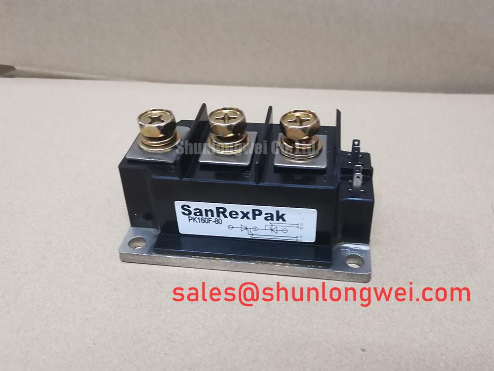
| Package | SanRex Power Module |
Measure the branch currents on each rectifier path while the DC power supply is operating at a controlled load, then compare the current balance before replacing an FRS200AA60 module. In a six pulse or twelve pulse rectifier arrangement, unequal branch current can arise from transformer phase imbalance, unequal busbar resistance, terminal contact condition, or an interphase transformer with an unsuitable current sharing characteristic. The 600.0 V voltage rating and 200.0 A current rating are Official Specifications for this SanRex module; system peak voltage, commutation conditions, and actual branch current require separate verification in the assembled rectifier.
For a high current green hydrogen electrolyzer DC power rectifier, the interphase transformer is used to support balanced conduction between parallel paths. Record each branch waveform with isolated measurement equipment and inspect for abnormal current displacement around commutation. A persistent imbalance may increase thermal stress in one path even where the average DC output appears stable. Design Consideration: keep equivalent conductor paths geometrically consistent so that parasitic resistance and inductance do not favor one rectifier branch during current transfer.
Fuse coordination must be based on the semiconductor fuse time current characteristic, its I2t capability, the anticipated fault-clearing path, and the system's prospective short-circuit current. Do not infer an I2t limit for FRS200AA60 from its 200.0 A current rating. Inspect terminal interfaces for discoloration, loss of clamping force, and conductor strain before returning the rectifier to service. Pro Tip: isolate all energy sources and verify a discharged DC link before loosening module terminals or measurement leads.
When a higher voltage member of the same family is being assessed, FRS200CA100 provides a neutral cross-reference for an engineering comparison of topology, terminal arrangement, and verified electrical boundaries rather than an assumed direct replacement.
FRS200AA60 Operational Boundaries: Evaluating Diode Peak Reverse Recovery Current and Surge-Current Limits
Capture the commutation waveform at the module terminals and inspect the reverse recovery interval whenever abnormal heating, fuse operation, or conducted noise appears after rectifier energization. Reverse recovery peak current and recovery softness influence the current transferred between conducting and blocking paths. Their observed severity depends on source inductance, transformer leakage, branch matching, temperature, and the external circuit rather than on the module's nominal current rating alone.
The provided Official Specifications establish 600.0 V and 200.0 A as the stated electrical ratings, but they do not establish a published Irrm, trr, or recovery softness value for this page. Engineering Recommendation: evaluate these switching characteristics using the original manufacturer documentation and a representative system waveform. This keeps the replacement assessment grounded in the actual commutation duty instead of assigning unsupported values to the module.
Minimize the commutation loop area where this reduces inductive overshoot, then verify peak terminal voltage against the DC-link condition during switching tests. The same principle applies to the DC supply and front-end arrangement. In systems that use a companion rectifier position, PK55FG120 can be reviewed as a related topology component, with its own ratings and connection requirements evaluated independently.
Gate-drive desaturation protection, soft turn-off behavior, and CMTI requirements belong to actively controlled power switches and their driver circuits. FRS200AA60 integration should distinguish those functions from diode or thyristor commutation behavior, avoiding protection assumptions transferred from an unrelated IGBT drive stage.
FRS200AA60 Operational Boundaries: Evaluating Baseplate Thermal Resistance Limits
Remove the module only after isolation, then inspect the heatsink imprint and thermal interface coverage across the full mounting face to identify uneven contact pressure. A local dry area, debris, warped heatsink surface, or uneven tightening sequence can raise the effective thermal path from the semiconductor junction through the baseplate to the heatsink. The supplied product facts identify a SanRex Power Module package, but no numerical junction-to-case thermal resistance is established in the provided official parameters.
Engineering Recommendation: use the original thermal specification for the installed module and assess pulse heating with the actual conduction waveform, ambient condition, heatsink performance, and coolant or airflow state. The measured case temperature is useful evidence, but it is not a substitute for a validated junction-temperature assessment during high-current pulses.
Apply thermal interface material as a controlled, continuous layer according to the interface-material guidance, and use the module drawing for fastener locations, tightening sequence, and torque. Avoid module distortion from uneven mounting pressure. Thermal margin is determined by the complete rectifier assembly, especially where parallel paths make one module carry more than its intended share.
For broader context on modular power conversion and efficiency tradeoffs, see The Race for Efficiency. SanRex's power semiconductor portfolio is also described by SanRex.
Assembly Integrity & Layout Architecture: Implementing Sinusoidal 10ms Half-Cycle Surge Current Limits for FRS200AA60
Review the event recorder and fuse status after an AC-side fault or transformer inrush incident, then confirm that reverse voltage was not reapplied until the rectifier path had been assessed. A sinusoidal 10 ms half-cycle surge test represents a specific short-duration stress condition; it does not authorize repeated field fault exposure or substitute for coordinated circuit protection. No ITSM value is included in the supplied Official Specifications, so this module page does not assign one.
Engineering Recommendation: obtain the applicable surge-current and thermal data from the original manufacturer documentation, then compare the recorded fault waveform, clearing behavior, and subsequent insulation checks with the system protection design. Inspect busbars, lugs, fuse holders, and terminal fasteners for evidence of heat or movement that can alter contact resistance during a surge.
Where controller assemblies use heavy leaded connections, the assembly process should account for the mechanical and thermal discipline associated with through-hole technology. Verify terminal connections against the rectifier drawing, maintain symmetric current paths where practical, and validate the completed assembly under controlled load before restoring electrolyzer service.