
Content last revised on March 27, 2026
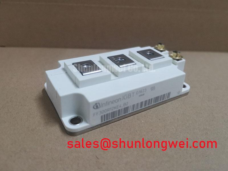
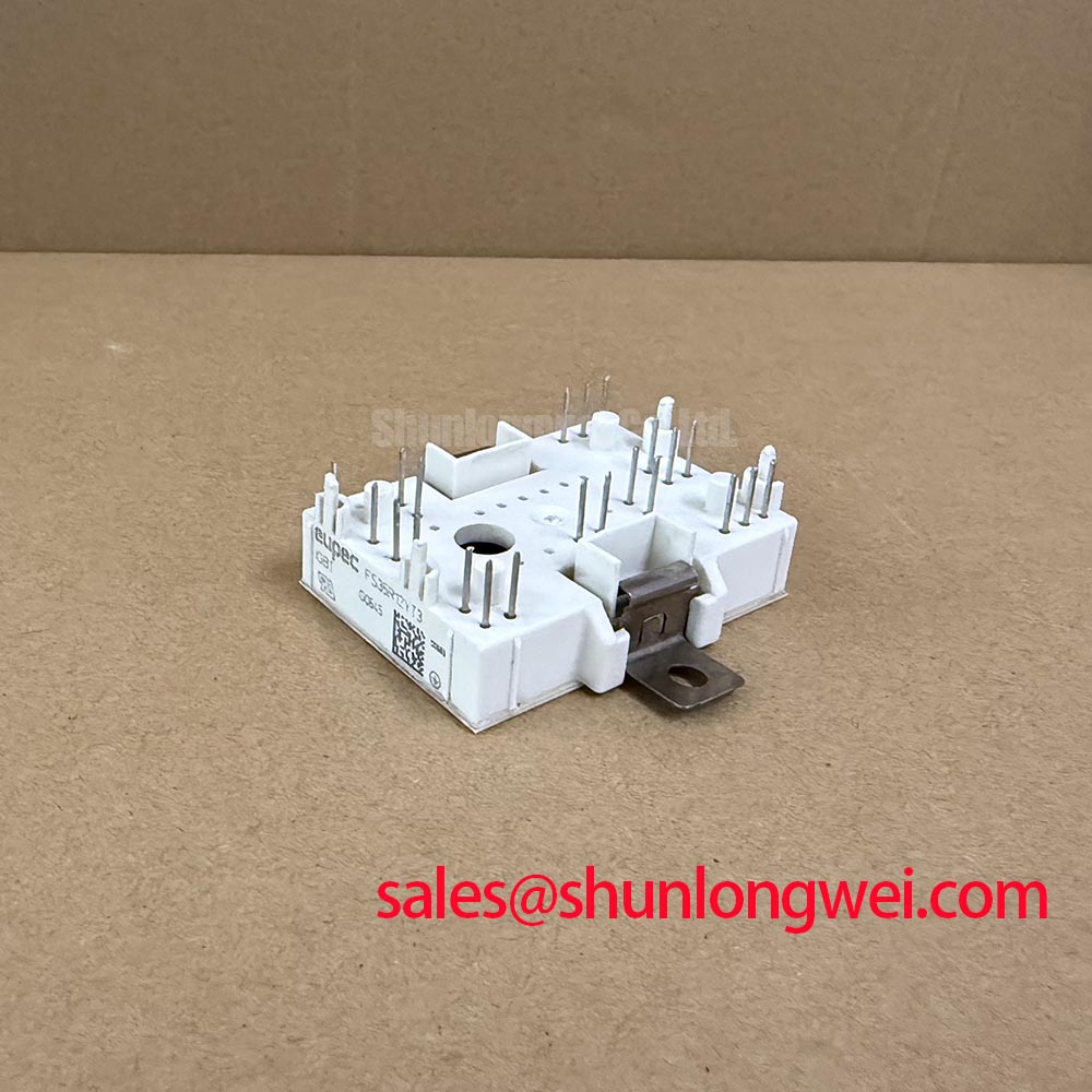
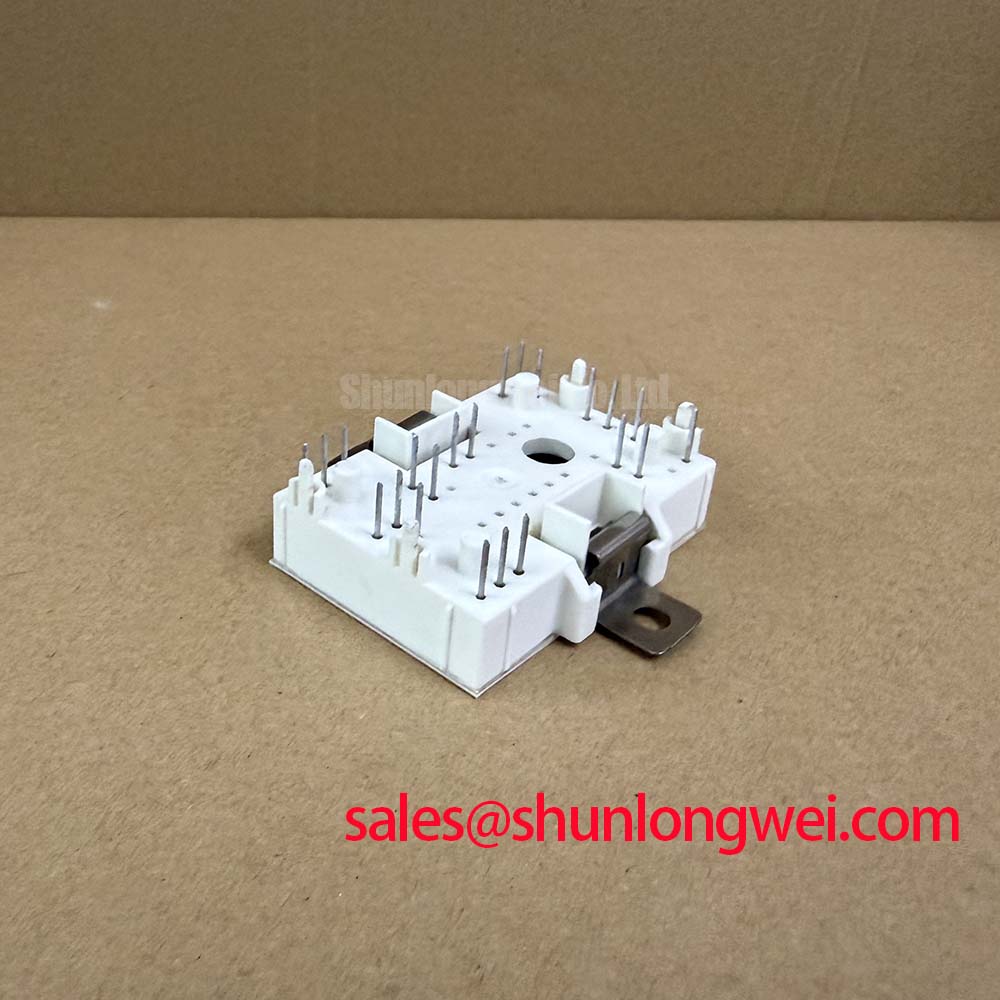
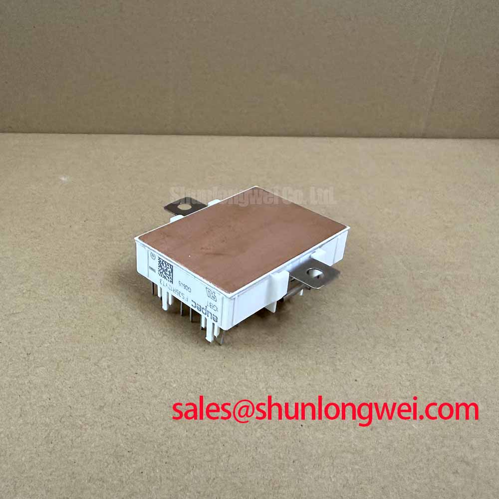
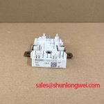
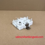
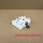
FS35R12YT3 Infineon TRENCHSTOP IGBT3 Sixpack Module
How does a designer maintain high power density in space-constrained industrial inverters without compromising on thermal headroom? The FS35R12YT3 provides a technical answer through the integration of the Infineon TRENCHSTOP IGBT3 chip technology within a compact EconoPACK housing. This module is specifically architected for engineers who require a reliable, sixpack configuration (three-phase inverter) capable of handling 1200V and 35A while minimizing conduction and switching losses. By incorporating an integrated NTC thermistor, the module simplifies the feedback loop for thermal protection, ensuring that the power stage operates within its safe boundaries even during peak load cycles.
UVP: Delivering optimized efficiency for mid-power industrial drives via TRENCHSTOP IGBT3 technology and integrated thermal sensing in a standardized sixpack footprint.
- Top Specs: 1200V Vces | 35A Ic | Vce(sat) 1.70V (typ)
- Key Benefits: Reduced system complexity via integrated NTC; superior switching robustness.
What is the primary benefit of the integrated NTC? It enables precise, real-time temperature monitoring at the module level, allowing the controller to dynamically adjust switching frequencies and prevent overtemperature failures. For 400V AC motor drive applications prioritizing long-term thermal stability, this 1200V module is a highly effective choice.
Frequently Asked Questions
Addressing Core Engineering Concerns for 1200V Systems
How does the TRENCHSTOP IGBT3 technology in the FS35R12YT3 impact overall inverter efficiency compared to older planar structures?
The TRENCHSTOP IGBT3 technology significantly reduces the Vce(sat) to approximately 1.70V, which acts like a lower-resistance valve in a hydraulic system. This lower conduction voltage drop means less energy is wasted as heat during the "on" state. When combined with the field-stop structure, it ensures a narrower distribution of switching times and lower Eoff, directly increasing the efficiency of Variable Frequency Drives (VFD) and Solar Inverters.
How does the Rth(j-c) of 0.85 K/W for the IGBT chips influence the selection of the external heatsink?
The Thermal Resistance (junction-to-case) of 0.85 K/W determines how efficiently heat moves from the silicon die to the module's baseplate. A lower Rth(j-c) allows for a more compact heatsink design or higher current density. Engineers must ensure the interface between the FS35R12YT3 baseplate and the heatsink uses high-quality thermal grease to maintain this low resistance, especially in high-ambient-temperature environments like industrial cabinets.
Key Parameter Overview
Decoding the Specs for Enhanced Thermal Reliability
| Main Technical Metric | Standard Value | Engineering Significance |
|---|---|---|
| Collector-Emitter Voltage (Vces) | 1200V | Suitable for 400V-480V AC line voltages with safety margin. |
| Continuous DC Collector Current (Ic) | 35A (at Tc=80°C) | Defines the maximum steady-state current handling capability. |
| Vce(sat) at Tj=125°C | 2.00V | Positive temperature coefficient supports safe paralleling. |
| Short Circuit Withstand Time (tsc) | 10 µs (at 125°C) | Provides essential window for Gate Drive protection activation. |
| Module Configuration | Sixpack | Three-phase bridge integrated into one housing for layout simplicity. |
Download the FS35R12YT3 datasheet for detailed specifications and performance curves from the official Infineon portal. Understanding the VCE(sat) calculation at varying temperatures is critical for precise loss estimation.
Technical Deep Dive
A Closer Look at the Trenchstop Technology for Loss Reduction
The core of the FS35R12YT3 performance lies in its TRENCHSTOP IGBT3 architecture. To visualize how this works, consider a traditional planar IGBT as a wide, shallow riverbed where water (current) meets significant turbulence (resistance) at the surface. The Trench structure "digs" vertical channels into the silicon, allowing the current to flow more vertically and densely. This reduces the Collector-Emitter Saturation Voltage (Vcesat), which is the electrical equivalent of reducing friction in a mechanical drive. Lower friction translates directly to less heat generation during high-frequency switching cycles.
Furthermore, the Field-Stop (FS) layer acts as a buffer that stops the electric field before it reaches the back-side collector, allowing for a thinner wafer. This thin-wafer technology is vital because it significantly lowers Switching Loss during the turn-off phase. In high-performance IGBT Modules, managing the trade-off between conduction losses and switching energy is the primary design challenge. The FS35R12YT3 balances these metrics to provide a robust solution for medium-power applications where active cooling might be limited. For systems requiring even more aggressive thermal management, understanding why Rth matters is essential for optimizing the heatsink interface.
Application Scenarios & Value
Achieving System-Level Benefits in High-Frequency Power Conversion
In the realm of Industrial Drive design, engineers often face the challenge of housing a three-phase inverter within a compact motor-mounted enclosure. The FS35R12YT3 addresses this by providing a complete sixpack topology in the EconoPACK package. This integration reduces the parasitic inductance that would typically occur with discrete components, thereby improving EMC performance and reducing voltage overshoots during high dv/dt switching events.
Consider a Servo Drive application used in robotic assembly lines. The high precision required in motion control demands an IGBT module that can switch reliably at frequencies between 8kHz and 15kHz. The FS35R12YT3's low Switching Loss allows for these frequencies without exceeding the thermal limits of the IGBT Module. While this 35A model is ideal for compact machinery, for systems requiring higher power handling, the related FS75R12KT3 offers a higher current rating of 75A within a similar technology family. Conversely, for smaller auxiliary drives, the FP25R12KT3 provides a more focused current capability.
Beyond motor control, this module is frequently utilized in Uninterruptible Power Supplies (UPS) and Solar Inverters. In these applications, the SCSOA (Short Circuit Safe Operating Area) of 10 µs is a critical safety parameter. It gives the system's protection logic sufficient time to detect a fault condition (such as a leg short-circuit) and shut down the gate signal before the silicon reaches destructive temperatures, ensuring system-level uptime and reliability in industrial 4.0 environments.