


Content last revised on September 10, 2026
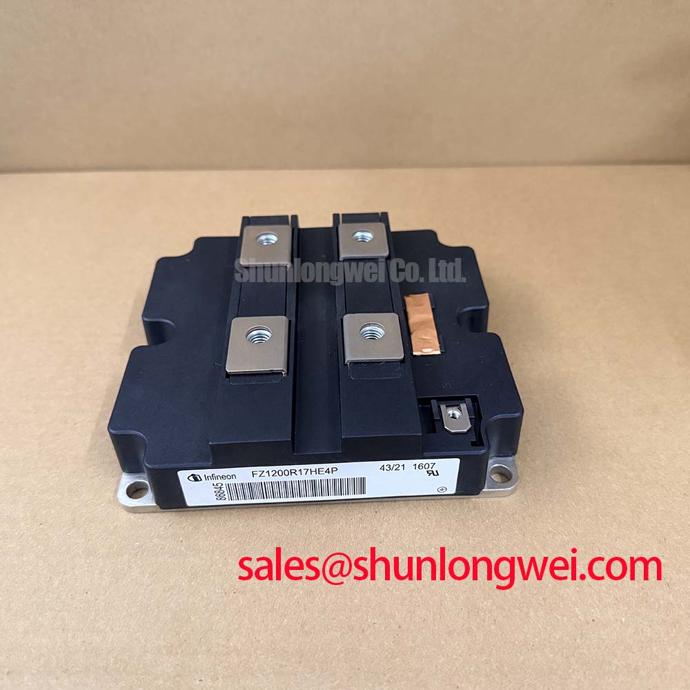
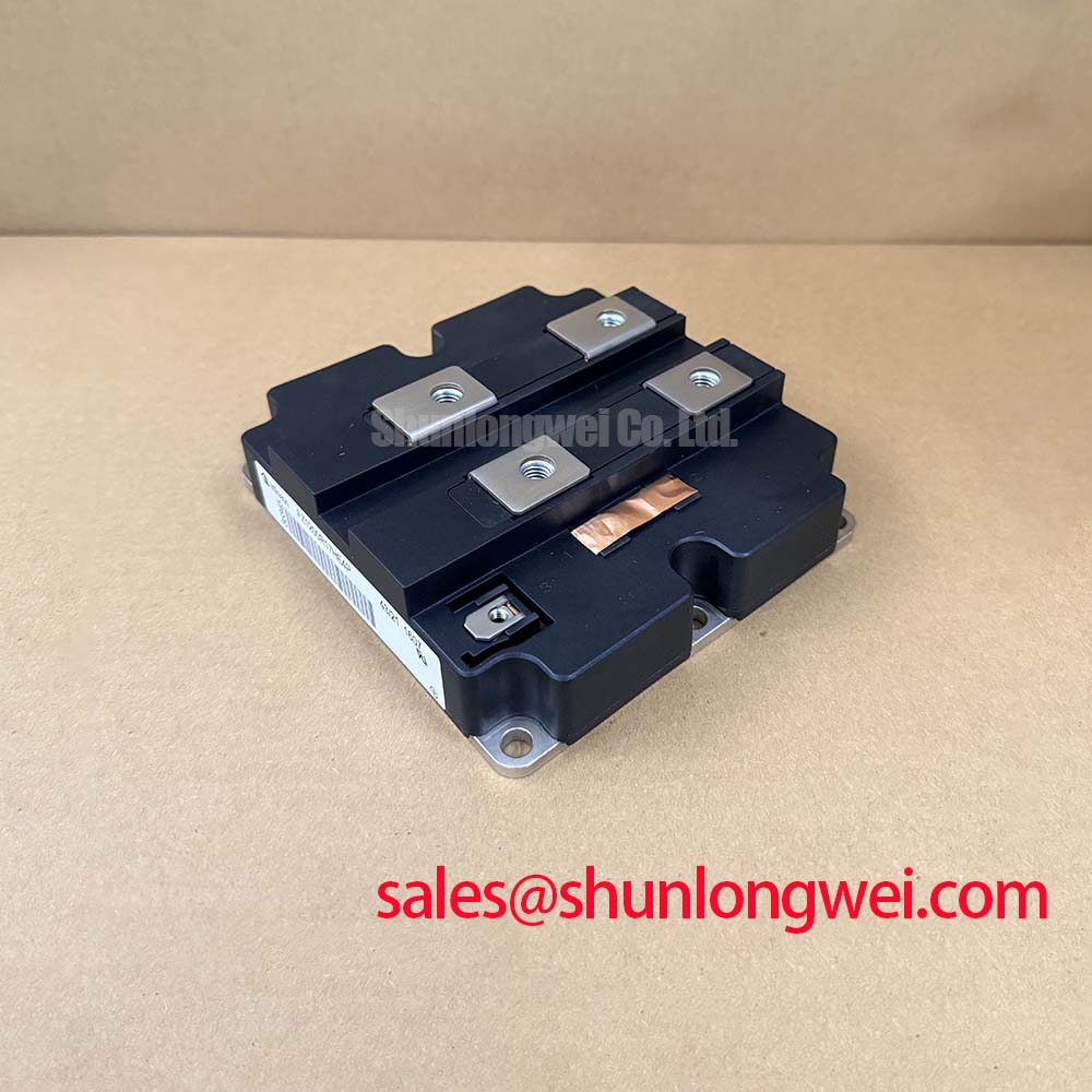
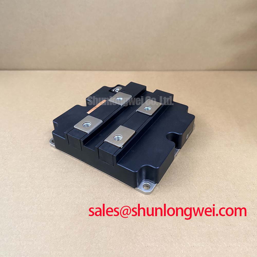
FZ1200R17HE4P Infineon IGBT Module: Optimizing Thermal Efficiency with Pre-Applied TIM
A high-performance single-switch IGBT module featuring pre-applied thermal interface material to maximize reliability and simplify high-power system integration. The FZ1200R17HE4P offers a 1700V blocking voltage, 1200A nominal current, and a low junction-to-heatsink thermal resistance of 23.4 K/kW. Key benefits include the elimination of manual paste application and reduced junction temperature fluctuations. What is the primary benefit of its pre-applied thermal interface material? Consistent thermal contact resistance by eliminating manual paste application. How does Trenchstop IGBT4 reduce energy loss? By utilizing a vertical trench gate structure that minimizes saturation voltage. For 1700V industrial drives prioritizing long-term thermal margin, this 1200A module is the optimal choice.
Application Scenarios & Value
Enhancing System Reliability in Harsh Industrial Environments
Engineers often face the critical challenge of managing intense thermal stress during high-power switching in large industrial drives and grid systems. In megawatt-class systems such as wind-to-grid conversion and heavy-duty traction converters, minimizing thermal interface variability is key to preventing premature power module failure. The module's 1700V collector-emitter voltage rating and 1200A continuous DC current capacity provide a robust safety margin during grid fluctuations. Furthermore, to comply with strict electromagnetic compatibility standards like IEC 61800-3 in industrial environments, stable gate control under high-dv/dt transients is indispensable. Integrating this module helps safeguard central inverter stages and high-capacity uninterruptible power supply (**UPS**) systems.
While this module is ideal for medium-to-high power platforms, systems requiring a standard thermal interface without pre-applied compound may utilize the related FZ1200R17HE4. For ultra-high power systems requiring even larger current density, the related FZ3600R17HE4 represents a scaled alternative.
Technical Deep Dive
Evaluating Pre-Applied TIM and Trenchstop IGBT4 Thermal Dynamics
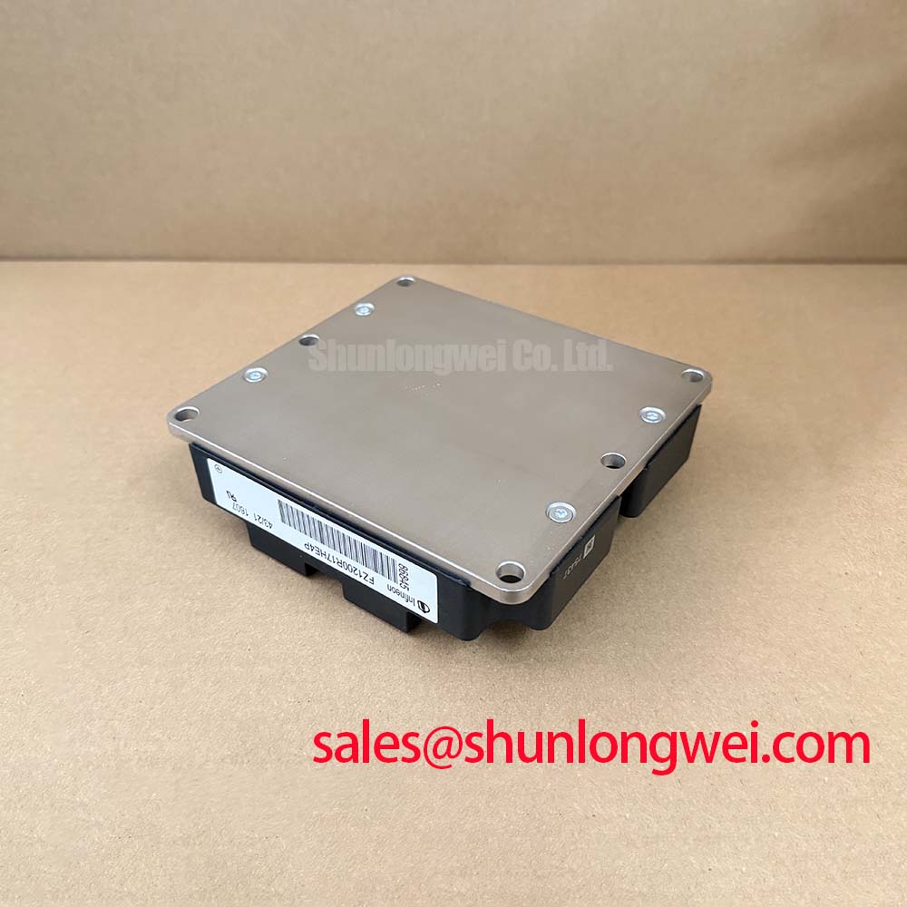
The suffix 'P' in the model name FZ1200R17HE4P explicitly denotes the inclusion of pre-applied thermal interface material. This factory-applied layer eliminates manual paste application, ensuring consistent thickness and preventing common assembly defects such as pump-out or voids. To understand how thermal interfaces dictate module life, engineers can review why Rth matters in IGBT thermal performance.
The pre-applied thermal interface material (TIM) acts like a highly engineered micro-level bridge, filling microscopic air pockets between the copper baseplate and the heatsink. Without it, these microscopic gaps act like thermal insulators—much like a thin layer of air trapped in a double-pane window—restricting heat transfer. By standardizing the TIM application at the factory level, the module achieves a stable thermal resistance from junction to heatsink (RthJH) of 23.4 K/kW per IGBT. Under the hood, Infineon utilizes Trenchstop IGBT4 technology. Consider this trench gate structure as an organized toll booth system: by arranging channels vertically rather than horizontally, it permits a higher concentration of charge carriers to pass through a smaller area. This vertical optimization reduces collector-emitter saturation voltage (VCE sat) to a typical 1.95 V (at 25°C), balancing conduction losses. Combined with an internal gate resistor (RGint) of 1.6 Ω, it mitigates voltage overshoots during fast turn-off transients.
Key Parameter Overview
Key Specifications for Advanced Thermal Reliability
The parameters below highlight the key electrical and thermal performance limits of the module as defined in the official technical documentation.
| Parameter | Specification Value | Engineering Value / Interpretation |
|---|---|---|
| Collector-Emitter Voltage (VCES) | 1700 V | Maximum blocking voltage capability at Tvj = 25°C. |
| Continuous DC Collector Current (IC nom) | 1200 A | Rated continuous current at heatsink temperature TH = 90°C. |
| Repetitive Peak Collector Current (ICRM) | 2400 A | Transient current handling limit (tp = 1 ms pulse width). |
| Collector-Emitter Saturation Voltage (VCE sat) | 1.95 V (Typical, Tvj = 25°C) | Indicates low conduction losses under full load. |
| Thermal Resistance, Junction to Heatsink (RthJH) | 23.4 K/kW (Per IGBT) | Performance metric utilizing the pre-applied thermal interface material. |
| Operating Junction Temperature (Tvj op) | -40°C to 150°C | Thermal operating window under dynamic switching conditions. |
Download the FZ1200R17HE4P datasheet for detailed specifications and performance curves.
Frequently Asked Questions
Addressing Design Constraints and Thermal Performance
How does the factory pre-applied TIM on the FZ1200R17HE4P compare to manual thermal paste application?
The factory pre-applied TIM ensures a uniform, optimized thickness across the copper baseplate. This eliminates common manual errors like excessive thickness or air gaps, stabilizing thermal resistance (RthJH) at 23.4 K/kW.
What is the impact of the 1700V rating on safety margins in 690V AC line systems?
In typical 690V AC systems, transient overvoltages require a minimum blocking voltage of 1700V. The 1700V rating provides a robust safety margin, preventing catastrophic avalanche breakdown during high-speed turn-off under inductive loads.
How does the RthJH of 23.4 K/kW affect heatsink sizing and system power density?
Reducing the thermal resistance barrier allows more efficient heat dissipation. Designers can either reduce heatsink size or operate the module at higher power density without exceeding the 150°C operating junction temperature limit.
What is the difference in gate drive requirements between this module and non-TIM versions?
The electrical gate drive requirements are identical. Both require a gate-emitter peak voltage of +/-20 V and benefit from an internal gate resistor of 1.6 Ω. The TIM version simply eliminates the manual paste application during mounting.
The industrial shift towards pre-applied thermal interface materials highlights a broader trend in Thermal Management: standardizing package-level interfaces to eliminate variables in high-volume assembly lines. As megawatt-class industrial drives and renewable energy inverters demand greater field lifetime, modules that integrate silicon optimization with structural consistency are becoming the preferred baseline for system architects seeking predictable, long-term reliability.