


Content last revised on March 27, 2026
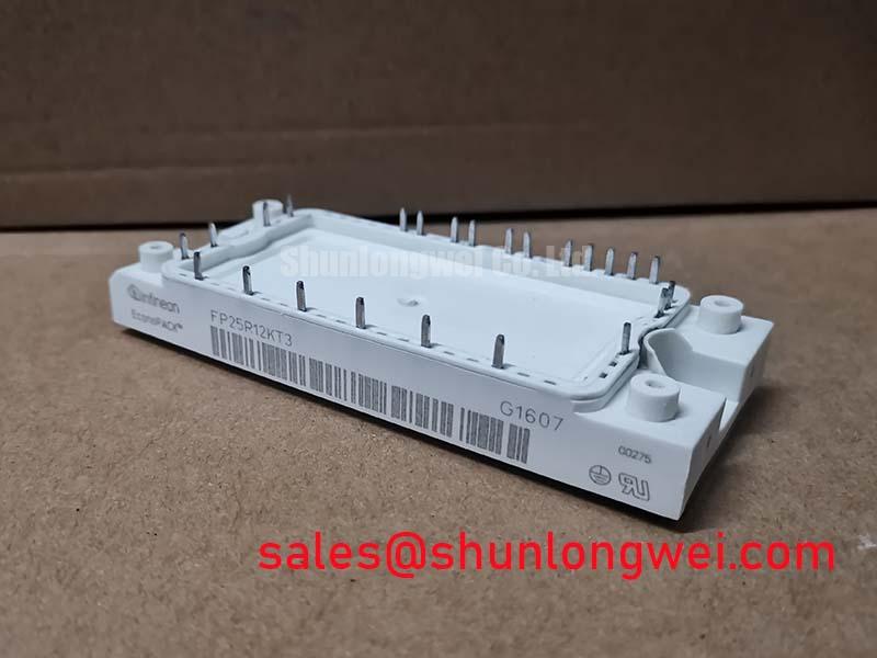
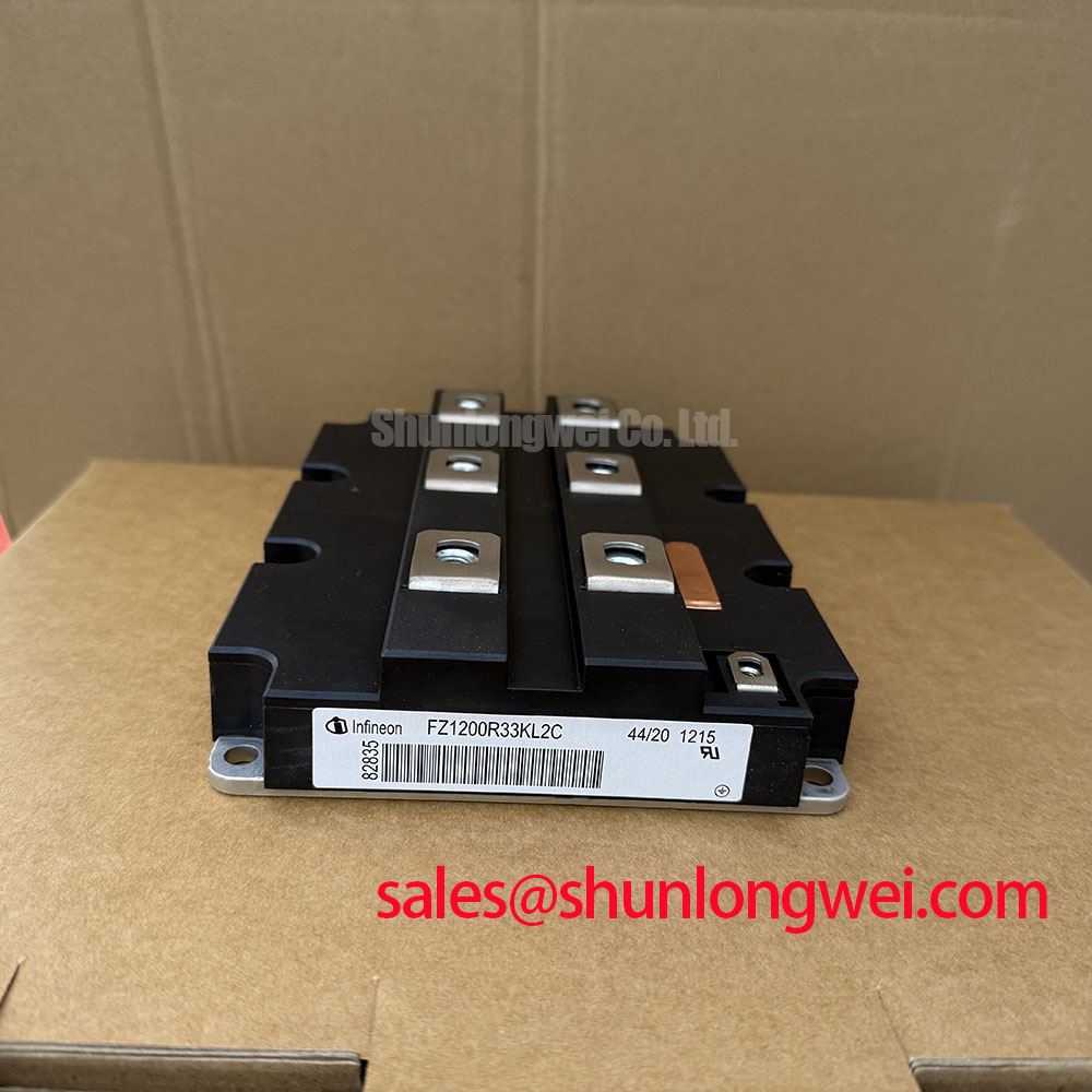
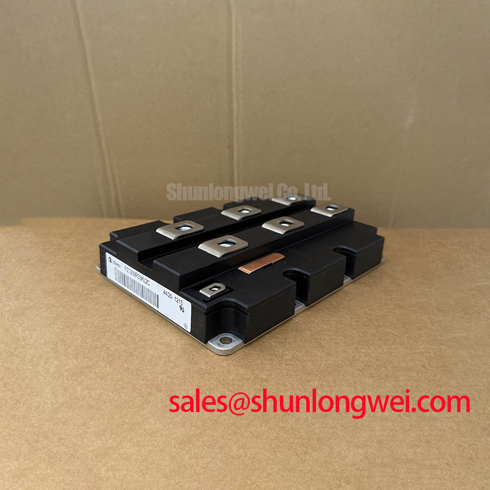
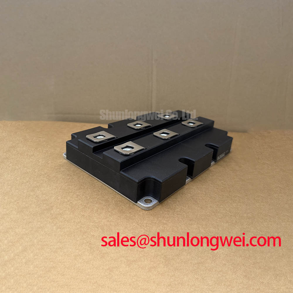
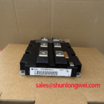
Infineon FZ1200R33KL2C 3300V 1200A Single Switch IGBT Module
Executive Overview of High-Voltage Switching Performance
Addressing DC Stability and Thermal Cycling Challenges in MW-Class Inverters
Can a single semiconductor switch maintain high-frequency efficiency while managing the brutal thermal fluctuations of a utility-scale wind turbine or a high-speed locomotive? The FZ1200R33KL2C answers this by leveraging Infineon Trenchstop technology and an advanced AlSiC baseplate to provide a 3300V | 1200A switching platform. This module is designed to minimize conduction losses while offering high RBSOA (Reverse Bias Safe Operating Area) ruggedness, ensuring that transient overvoltages do not lead to catastrophic failure.
What is the primary benefit of its AlSiC baseplate? It significantly extends the power cycling lifetime by matching the thermal expansion coefficient of the internal ceramic substrates. For 3.3kV railway traction systems requiring maximum uptime and minimal maintenance, the FZ1200R33KL2C is the optimal technical choice.
Technical FAQ
Solving Implementation Challenges in High-Voltage Environments
How does the AlSiC baseplate in the FZ1200R33KL2C influence long-term reliability compared to standard copper baseplates?
Standard copper baseplates have a higher coefficient of thermal expansion (CTE) mismatch with the internal ceramic (AlN) isolation. Under the heavy thermal cycling found in traction and grid applications, this mismatch can lead to solder fatigue and delamination. The AlSiC (Aluminum Silicon Carbide) baseplate used here provides a CTE much closer to the ceramic substrate, drastically increasing the Power Cycling Capability and extending the operational life of the module under variable load conditions.
What considerations are required for the 10.2kV insulation test voltage of this module?
The FZ1200R33KL2C is rated for an insulation test voltage of 10.2kV (RMS, 50Hz, 1 min), which is critical for 3300V applications to meet IEC 61287-1 standards. Engineers must ensure that external busbar design, potting, and mounting environments maintain sufficient clearance and creepage distances to prevent tracking or partial discharge, especially at high altitudes or in high-humidity environments.
Key Parameter Overview
Technical Specifications for Engineering Evaluation
| Symbol | Parameter Description | Typical Value | Unit |
|---|---|---|---|
| Vces | Collector-Emitter Voltage | 3300 | V |
| Ic | Continuous DC Collector Current (Tc=80°C) | 1200 | A |
| Icrm | Repetitive Peak Collector Current (tp=1ms) | 2400 | A |
| Vce(sat) | Collector-Emitter Saturation Voltage (Ic=1200A, Tvj=125°C) | 3.45 | V |
| Vge(th) | Gate Threshold Voltage | 4.2 to 6.4 | V |
| Visol | Isolation Test Voltage (RMS, f=50Hz, t=1 min) | 10.2 | kV |
| Rthjc | Thermal Resistance, Junction to Case (per IGBT) | 11.0 | K/kW |
Download the FZ1200R33KL2C datasheet for detailed specifications and performance curves.
Technical Deep Dive
Advanced Trenchstop Technology and Low-Loss Switching Dynamics
The FZ1200R33KL2C utilizes the Infineon TRENCHSTOP™ IGBT3 chip architecture, which serves as the "brain" of the power stage. To visualize this technology, think of the trench structure like an efficient multi-lane highway system built vertically into the silicon. Unlike older planar technologies that required wider "roads" to handle high voltage, the trench design allows for a higher carrier density in the on-state. This directly results in a lower Vce(sat), reducing the heat generated during the conduction phase. For a module handling 1200A, even a fractional reduction in saturation voltage translates to hundreds of watts in saved energy across the system.
Furthermore, the module incorporates a Soft-Switching diode characteristic. In high-power Variable Frequency Drives (VFDs), the rapid turn-off of the IGBT can cause significant voltage spikes due to stray inductance. The internal EmCon (Emitter Controlled) diode is tuned to provide a soft recovery, minimizing electromagnetic interference (EMI) and reducing the stress on the Gate Drive and insulation systems. This balance between switching speed and softness is a hallmark of the IHM-B package series, allowing for higher power density without sacrificing RBSOA safety margins. For further insight into these mechanisms, engineers may refer to our guide on in-depth IGBT analysis and failure prevention strategies.
Application Scenarios & Value
Optimizing Heavy Industrial and Traction Power Stages
The FZ1200R33KL2C is predominantly utilized in Railway Traction and HVDC (High Voltage Direct Current) transmission projects. In a locomotive traction inverter, the module must handle the immense surge currents during startup while operating reliably under the constant vibration and temperature cycling of long-haul transport. The 3300V rating is specifically tailored for 1500V DC overhead line voltages, providing a robust safety overhead for voltage transients. Utilizing this module allows for a simplified two-level or three-level topology, reducing the total component count and improving the Mean Time Between Failures (MTBF) for the overall system.
In the renewable energy sector, specifically for offshore wind converters, the FZ1200R33KL2C provides the necessary current density to manage MW-class power blocks. The integration of high-reliability AlSiC baseplates ensures that the module survives the saline, high-humidity environments where maintenance is prohibitively expensive. For designs requiring comparable voltage but different current handling or topology, the FZ1200R33KF2C or the dual-switch FF400R33KF2C may be evaluated to meet specific power stage requirements. These solutions collectively support the global shift toward High-Efficiency Power Systems and the stringent demands of modern Grid-to-Wind conversion.