Content last revised on September 12, 2026
Transient Dynamics & Electrical Design: Four Quadrant Power Flow Topologies for Grid Connected FZ1500R25KF1 Systems
For a utility scale centralized battery energy storage power conversion system, start fault isolation by confirming whether the disturbance appears during battery discharge, battery charge, grid synchronization, or a power direction reversal. Four quadrant operation requires the converter to manage active power flow in both directions while the DC battery racks and AC side impose different transient conditions. A failure that emerges only after a direction change can involve the module, but it can also originate in current sensing, gate command timing, DC link contactors, precharge behavior, control firmware, or a disturbed voltage reference.
The 2500 V rating is an Official Datasheet Specification for the FZ1500R25KF1. It is not a substitute for a complete system transient study. During switching, the voltage observed at a module terminal can differ from the nominal DC link because stray inductance, commutation current, busbar geometry, snubber condition, and gate drive behavior all influence the waveform. As a Design Consideration, keep the high current commutation path compact and physically symmetrical where the existing converter architecture permits. The system engineer should verify peak collector emitter voltage and current waveforms at the installed switching condition rather than relying on DC measurements alone.
In field repair work, inspect laminated busbars, terminal faces, fasteners, and DC link capacitor connections before fitting a replacement module. Discoloration around a joint, an uneven contact mark, loosened hardware, or damaged insulation spacing can alter current commutation and cause repeat faults after a module change. Remove contamination from mating surfaces according to the equipment maintenance procedure. Confirm that the installed phase leg arrangement, gate driver harness routing, and terminal sequence agree with the equipment drawings before applying auxiliary power.
Battery energy storage converters often experience repeated current reversals during peak shaving, charging windows, and grid support commands. Those cycles can create varying device losses and thermal movement across the power stage. A Design Consideration is to compare heatsink temperature trends, coolant flow or fan operation where applicable, and phase to phase loading before attributing a protection trip to the IGBT module. A thermal issue can present as a delayed trip after several power cycles, while a gate loop or measurement issue may become visible immediately at the first switching command.
When evaluating another Infineon module family for a different voltage and current envelope, the FZ3600R12HP4 can be reviewed as a separate product reference. It should not be treated as a drop in replacement for the FZ1500R25KF1. Voltage class, current class, mechanical dimensions, terminal arrangement, driver requirements, cooling interface, control timing, and protection calibration must be checked against the original system requirements.
For teams reviewing semiconductor behavior in three phase conversion hardware, The 1200 V CoolSiC™ MOSFET Advantage in Three provides a related technical reference for waveform evaluation and power conversion architecture. It does not establish operating limits for this 2500 V IGBT module. System level voltage margins, altitude conditions, surge exposure, and switching stress require verification for the actual PCS installation.
FZ1500R25KF1 Circuit Protection & Reliability: Calibrating Isolated DC DC Power Supply Sizing for High Energy Gate Drive Systems
Before reconnecting the driver board, inspect the isolated DC DC supply rails under their intended load and confirm that the gate driver protection output is not held in a fault state. A gate driver can produce misleading symptoms if its isolated supply is unstable, its desaturation network is damaged, its fiber or digital isolation link is interrupted, or its local reference has shifted. The module should be installed only after the driver assembly, gate connectors, and protection interlock path have been checked against a known good phase or the original maintenance documentation.
Reinforced galvanic isolation and common mode transient immunity are properties that must be verified from the specific gate driver and isolated power supply documentation. They are not confirmed product specifications of the FZ1500R25KF1 from the available information. In a high energy converter, Design Consideration calls for an isolation system capable of maintaining command integrity during fast switching common mode events. The system designer should verify the relevant insulation ratings, creepage and clearance requirements, and transient immunity requirements against the installed DC link and control architecture.
Where multiple power modules are used in parallel, static and dynamic sharing are system concerns. The temperature dependence of collector emitter saturation behavior can influence static sharing, but it does not remove the need for matched interconnects and verified driver timing. Use symmetrical busbar routing, comparable thermal paths, and equivalent gate loop placement as Design Considerations. During commissioning, measure phase current and, where the test setup permits, compare switching waveforms across parallel positions. A current imbalance may indicate unequal path resistance, unequal inductance, driver variation, uneven cooling, measurement offset, or a device issue; it should not be assigned to one cause without evidence.
Protection coordination should be examined from the controller command through the gate driver and into the power stage. Confirm that the controller dead time strategy prevents unintended simultaneous conduction in the relevant bridge leg. The required timing is system determined because it depends on the actual driver, switching behavior, operating temperature, current level, and converter topology. A scope capture referenced to the correct local emitter or driver return point is generally more informative than measurements made across long ground leads, which can introduce apparent ringing that is not present at the gate terminals.
The wider Infineon power semiconductor portfolio is described in the Infineon IGBT Modules & Discretes Official Portfolio. Product family information is useful for understanding the manufacturer’s portfolio, while the original equipment circuit and the specific FZ1500R25KF1 documentation remain necessary for service decisions.
In converter systems that use a separate front end rectifier, a device such as FZ800R12KS4_B2 may appear in related power conversion stages. It is a distinct component with its own electrical and mechanical characteristics. Its presence in a system does not determine the compatibility, gate drive requirements, or service limits of the FZ1500R25KF1.
Benchtop Waveform Tuning: Mitigating Hard Switching Transients via Active Protection on FZ1500R25KF1
After a module replacement, energize the control section first and verify gate commands, interlocks, and fault feedback before allowing the main DC link to operate. Bench troubleshooting should begin with a controlled test condition defined by the equipment manufacturer or qualified system engineer. Observe the gate emitter signal, collector emitter behavior, current feedback, and fault output together. Looking at only the gate waveform can conceal a current sensor fault, while looking only at current can conceal a driver supply collapse or a protection event.
Short circuit protection timing, desaturation detection, and soft turn off behavior belong to the driver and system protection design unless the applicable module datasheet states otherwise. The FZ1500R25KF1 available product data does not establish a specific short circuit withstand interval, protection response time, gate voltage, clamp value, or gate resistance. Do not transfer these values from another module family. As an Engineering Recommendation, confirm the installed driver’s response sequence from the original schematic and test records, then verify that a detected overcurrent produces a controlled gate response without creating an excessive inductive voltage excursion.
Hard switching stress is influenced by the interaction of power loop inductance, DC link capacitor placement, gate loop impedance, current direction, temperature, and driver behavior. The practical objective is to minimize unintended parasitic inductance in the commutation and gate paths so that turn off overshoot and oscillation are controlled. The final damping method, switching rate, and protective clamp settings are determined by the converter design and should be validated with measured peak waveforms under representative operating conditions.
When an oscilloscope shows irregular gate ringing, inspect the gate return path, connector seating, shield termination, driver mounting, and nearby power conductor routing before changing components. A ringing waveform may indicate a parasitic loop issue, a probe connection artifact, insufficient driver reference integrity, or a changing power stage condition. Compare the suspect phase with a known good phase using the same probe method and measurement location. This comparison often gives a clearer direction than attempting to judge a waveform against a generic image.
Field Alert: Disconnect and verify discharge of all DC link energy before inserting or removing a gate driver connector, because an unintended gate command can occur if auxiliary supplies remain active.
For high voltage industrial power modules, the operating environment also deserves disciplined review. No sourced field data is available here to quantify cosmic ray exposure, single event burnout risk, altitude derating, lifetime, or failure rates for this product. These subjects should therefore be treated as Design Considerations. The system owner should use the original equipment requirements, site installation conditions, and manufacturer documentation when evaluating insulation coordination, environmental stress, and protection margins.
Preventing Spurious Faults: Thermal Interface Material Thickness Uniformity Guidelines for FZ1500R25KF1
Before tightening the FZ1500R25KF1 to the cooling surface, inspect the module base contact area and the heatsink or cold plate for scratches, raised debris, corrosion, trapped old compound, and localized distortion. A power module can exhibit a protection trip under load when the thermal interface is uneven, but the same symptom can also arise from restricted coolant flow, failed fans, poor temperature sensing, uneven clamp force, abnormal switching loss, or an overload event. Thermal inspection should be part of a broader fault review.
Use the thermal interface material specified by the equipment manufacturer and apply it in a thin, continuous, uniform layer. Thickness selection, material type, and application method are Design Considerations unless established by the original converter documentation. The objective is to fill microscopic surface irregularities without creating a thick insulating layer or leaving air pockets. If a removed module shows a visibly incomplete contact pattern, inspect both mating faces and the mounting sequence before assuming that the replacement part is responsible.
Mounting screws should be tightened in the prescribed order and to the torque stated by the original equipment documentation or applicable mechanical drawing. A sequential cross pattern is commonly used as a Design Consideration to distribute clamping load progressively across the baseplate. Do not use a general torque value as a mandatory setting for this module because screw size, thread condition, hardware stack, heatsink material, and equipment design determine the correct requirement.
After commissioning, compare operating temperatures and fault history across equivalent power positions where the controller provides reliable data. A phase that heats differently from its peers may require review of thermal interface contact, cooling path condition, current sharing, driver timing, sensor placement, and load distribution. If a thermal alarm occurs only after prolonged power transfer, record the actual load profile and cooling conditions before removing the module. This preserves evidence that can distinguish a cooling problem from a switching or control problem.
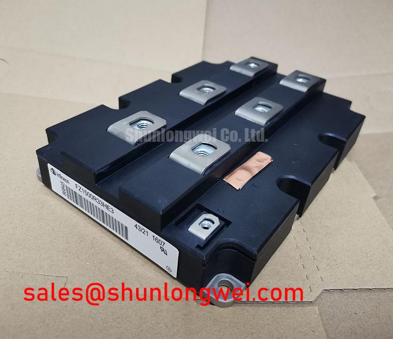
The FZ1500R25KF1 is identified by its official 2500.0 V and 1500.0 A ratings in a Module package. For a utility scale battery energy storage PCS, safe integration depends on matching those product identity specifications with the original converter topology, verified gate driver behavior, protective coordination, busbar geometry, and thermal assembly process.