Content last revised on September 25, 2026
CM1200HB-66H Circuit Protection & Reliability: Calibrating Galvanic Gate Drive Isolation, Reinforced
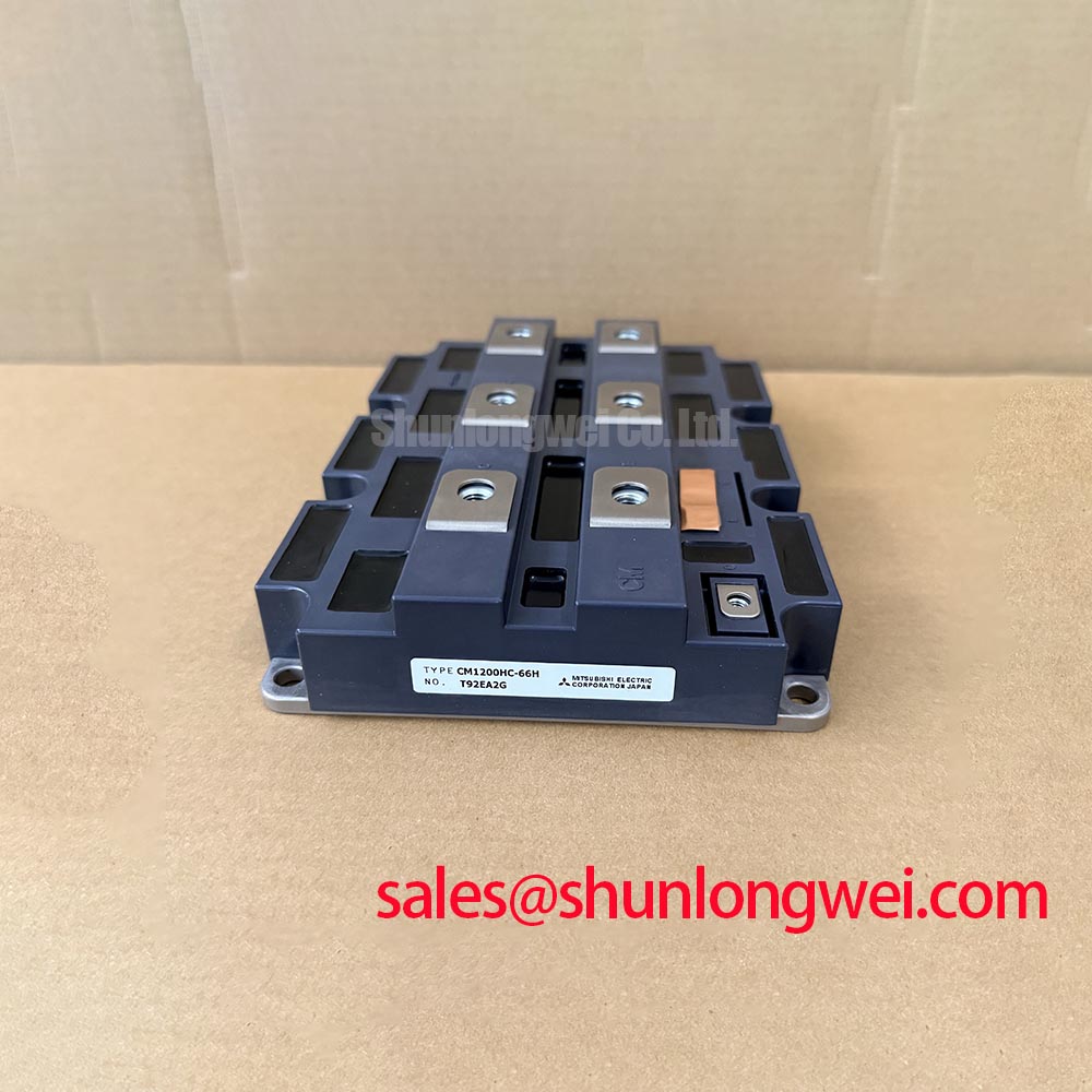
Before installation, verify the nameplate rating against the converter documentation and inspect the CM1200HB-66H housing, power terminals, and mounting surface for transport damage, contamination, or evidence of uneven prior clamping. This Mitsubishi Electric IGBT Module is rated at 3300 V and 1200 A as an Official Specification, supplied in a module package. These ratings define the device identity, but they do not replace verification of the original inverter’s gate driver, snubber network, fuse coordination, cooling assembly, and protection thresholds.
For maintenance planning, treat the module as part of a complete power-switching assembly rather than an isolated replacement item. Before energizing a repaired cabinet, confirm that the DC-link discharge procedure has been completed, that gate-drive connectors are correctly seated, and that the heatsink interface is clean. Mitsubishi Electric’s Power Semiconductors and High-Power Modules information provides useful manufacturer-level context when checking the original equipment documentation and approved operating conditions.
| Parameter | Value | Classification |
|---|---|---|
| Product model | CM1200HB-66H | Official product identification |
| Manufacturer | Mitsubishi Electric | Official manufacturer identification |
| Rated voltage | 3300 V | Official Specification |
| Rated current | 1200 A | Official Specification |
| Package | Module | Official Specification |
In a high-power converter repair, begin at the isolation boundary between the control electronics and the power stage. The CM1200HB-66H operates in a voltage class where switching-node movement can disturb gate-drive circuits through parasitic capacitance, cable routing, contamination, or inadequate separation between control and power conductors. A galvanically isolated driver should therefore be evaluated as a complete channel, including its isolated supply, driver output path, measurement connections, and shutdown behavior.
Reinforced isolation capability and common-mode transient performance belong to the selected gate-driver system, not to the IGBT module’s published 3300 V and 1200 A ratings. As a Design Consideration, the integrator should confirm isolation ratings and transient immunity from the driver manufacturer’s documentation, then validate behavior at the actual switching conditions of the equipment. It is not appropriate to assume a particular isolation withstand level or common-mode transient immunity figure from the module designation alone.
During troubleshooting, compare a suspected phase leg with a known-good phase where the original design allows it. Look for unintended gate pulses, unequal gate-emitter waveforms, delayed desaturation response, or noise entering the low-voltage control reference. These observations can indicate several issues, including degraded isolated power delivery, an unsuitable measurement ground connection, poor routing, or a driver fault. Oscilloscope probing should be performed with an isolation method appropriate to the voltage and measurement location.
Clearance and creepage distances must follow the insulation coordination requirements of the finished equipment, the local pollution environment, and the applicable system standard. Keep high-energy power paths physically separated from low-level feedback paths, particularly where the gate-drive connector and controller harness leave the power compartment. Cable shields and chassis bonding should be reviewed against the original equipment architecture rather than changed in isolation, because an apparently minor wiring change can alter return-current paths.
For a utility-scale central photovoltaic inverter, the module may be evaluated as part of a power conversion stage, subject to confirmation of the original topology and voltage stress. The inverter’s nominal DC system voltage does not by itself establish the semiconductor’s real switching peak, fault condition, or transient margin. Designers should verify those conditions on the equipment waveform and against the original qualified design.
Preventing Spurious Faults: Negative Gate Bias vs Active Miller Clamp Guidelines for CM1200HB-66H
A gate that appears to be held off at the driver output can still experience a transient rise at the module gate terminals when the opposite switch changes state. This is a circuit-level effect involving the gate loop, the power loop, driver impedance, layout, and switching rate. The CM1200HB-66H should be connected only through a gate-drive arrangement verified for the original converter’s switching sequence and protection strategy.
Negative gate bias and an active Miller clamp are alternative or complementary control methods selected by the system designer. Neither is an Official Specification of this module based on the available product data. A negative bias arrangement can increase off-state gate margin, while an active Miller clamp can provide a low-impedance path intended to restrain transient gate movement after turn-off. Their suitability depends on the driver’s allowed output range, the module’s gate requirements in the applicable manufacturer documentation, protection coordination, and measured switching waveforms.
Do not copy gate resistance, negative bias, dead-time, or clamp settings from an unrelated module or inverter. These are system-determined values. As an Engineering Recommendation, minimize parasitic inductance in the gate path to reduce ringing and unintended coupling, then verify the resulting collector-emitter and gate-emitter waveforms during switching tests. The test should check both normal commutation and the operating conditions that are most likely to reveal overshoot, oscillation, or false protection trips.
A high-side isolated supply or bootstrap-derived supply requires enough stored energy to support the driver’s gate-charge demand, quiescent consumption, timing interval, and voltage tolerance during the required on-time. The capacitor selection is an Engineering Calculation based on the specific driver’s gate charge, supply current, switching frequency, and permitted supply-voltage variation. Since those driver-specific values are not Official Specifications of the CM1200HB-66H, the original gate-driver data must govern the calculation.
When a repaired converter produces intermittent overcurrent or gate-drive alarms, inspect the gate-loop return path, driver supply stability, connector contact condition, and controller-to-driver isolation before attributing the event to the power module. Confirm that desaturation or short-circuit protection behavior matches the original control design. Fast protection coordination is especially important because a short-circuit event can place severe electrical and thermal stress on a high-power IGBT assembly.
⚠️ Maintenance Note: During scheduled service, monitor terminal and heatsink contact temperature trends under comparable load conditions and confirm that cooling-air passages remain free of dust accumulation.
Preventing Spurious Faults: Atmospheric Neutron Radiation Impact Guidelines for CM1200HB-66H
Atmospheric neutron exposure, altitude, DC-bus stress, and single-event burnout are high-risk reliability topics that require device-specific qualification evidence. No FIT rate, altitude derating figure, burnout probability, or operating-life prediction should be inferred from the available 3300 V, 1200 A, and module-package information for the CM1200HB-66H.
As a Design Consideration, equipment intended for elevated locations should be assessed using the power-semiconductor manufacturer’s applicable reliability material, the inverter manufacturer’s environmental specification, the actual DC-link operating range, and the site’s installation conditions. The system team should determine whether altitude changes cooling effectiveness, insulation coordination, transient exposure, or semiconductor stress margins. These factors are related but must not be collapsed into a single assumed failure mechanism.
For preventive maintenance, record the actual operating environment rather than relying on generic assumptions. Useful observations include cabinet temperature, fan condition, filter cleanliness, condensation evidence, corrosion around bus connections, alarm history, DC-link waveform quality, and repeated nuisance-trip patterns. A gradual increase in temperature or irregular switching waveform can have many causes, such as cooling degradation, driver instability, poor terminal contact, control timing changes, or load-side disturbances.
Where a central solar inverter experiences unexplained power-stage trips, compare logged DC-link behavior and phase-current records with weather, grid, and thermal conditions. Verify the condition of surge-protection components, reactor connections, current sensors, and the control supply. Long output cables can also create reflected voltage phenomena at the motor or load end in applicable converter systems; filter selection and cable compatibility remain system-level decisions that require measurement and validation.
Engineers evaluating alternative device families for a redesign can use the technical discussion in The 1200 V CoolSiC™ MOSFET Advantage in Three as a general technology reference. That material concerns a different voltage class and device technology, so it should not be treated as a direct electrical substitute specification for the CM1200HB-66H.
CM1200HB-66H Operational Boundaries: Evaluating Baseplate Convexity Compensation and Screw Limits
Before mounting the CM1200HB-66H, inspect the heatsink for flatness, scratches, embedded debris, corrosion, and residue from aged thermal material. A clean mating surface is necessary for a consistent thermal interface. The module’s 1200 A current rating does not establish the thermal capability of the assembled converter, because usable thermal performance also depends on heatsink condition, airflow or liquid cooling performance, interface material, mounting pressure, ambient conditions, switching losses, and load profile.
Thermal interface material thickness and mounting torque are Design Considerations unless specified by the original Mitsubishi Electric documentation for this exact assembly. The purpose of the interface is to fill microscopic surface irregularities without creating an unnecessarily thick thermal path. Apply material in accordance with the original equipment procedure and the thermal-material supplier’s instructions. Avoid contaminating electrical terminals, gate connections, or nearby insulation surfaces.
Baseplate curvature and heatsink flatness can affect pressure distribution. If a module is clamped unevenly, some regions can develop poorer thermal contact even when the assembly appears mechanically secure. Use the mounting sequence defined by the equipment manufacturer or module documentation. Tightening should be progressive and balanced across the mounting points so the module is seated evenly against the heatsink. The final screw torque must be verified from the applicable official mechanical documentation; it should not be guessed from a generic fastener rule.
After reassembly, inspect busbar alignment before final tightening. Busbars that pull sideways on terminals can introduce mechanical stress and may impair contact consistency. Confirm that terminal hardware, insulating barriers, and protective covers are restored exactly as required by the equipment design. If a replacement assessment requires comparison with another Mitsubishi Electric module family, CM50DY-28H can be reviewed as a separate product reference, but its voltage, current, package, circuit configuration, mounting geometry, and gate-drive compatibility must be independently verified before any engineering decision.
Following service, perform controlled functional checks with the converter’s prescribed safety procedures. Review phase-current balance, heatsink temperature behavior, gate-drive fault reporting, DC-link stability, and cooling-system operation. Reinspect terminal tightness and thermal-management condition at the equipment’s normal preventive-maintenance interval, especially where dust, humidity, or condensation can affect the cabinet environment.