Content last revised on October 9, 2026
Desaturation (V_CE(sat)) Detection & Two-Stage Soft Turn-Off Short-Circuit Protection
Start a desaturation-trip investigation at the disconnected power stage. Inspect the terminals, insulating surfaces, gate connections, and driver-board components for loose connections, discoloration, or visible damage. Compare low-energy multimeter measurements with the equipment's service procedure and a known-good equivalent circuit, where available. A low collector-to-emitter impedance may indicate a failed device, but parallel semiconductor paths must be excluded before drawing that conclusion.
| Product characteristic | Confirmed value | Specification identity |
|---|---|---|
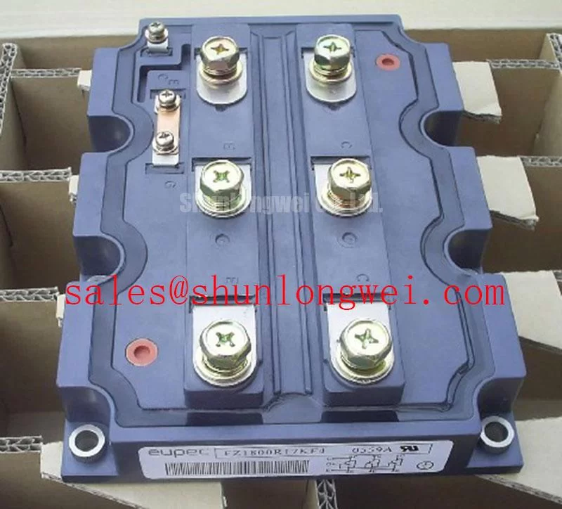
| Model | FZ1800R17KF6C_B2 | Product designation |
| Manufacturer | Infineon | Manufacturer identification |
| Rated voltage | 1700 V | Official Specification |
| Rated current | 1800 A | Official Specification; apply the manufacturer's rating conditions |
| Package | Module | Official Specification |
Design Consideration: Desaturation protection monitors the collector-to-emitter voltage while the IGBT is commanded on. An unexpected rise can be associated with excessive current, inadequate gate drive, or a problem in the sensing circuit. The detector's threshold and blanking interval belong to the driver design; neither can be derived from the module's voltage and current ratings. Check the sensing diode, return path, connector continuity, and fault latch before assuming that every desaturation event represents a shorted power device.
Protection must address both a switch turning on into an existing short circuit and a short circuit developing during conduction. Their detection waveforms need not be identical. The permissible total response time must come from the model-specific short-circuit safe operating area and its stated test conditions. Do not assign this module a short-circuit withstand interval from another IGBT family's documentation.
Design Consideration: Two-stage soft turn-off can reduce the abrupt current change associated with fault interruption. The first stage controls the gate discharge; the subsequent stage establishes the off state. Whether this strategy is appropriate depends on the available fault-energy margin, gate-driver behavior, and power-loop inductance. Verify detection delay, gate response, and collector-voltage overshoot using appropriately rated measurement equipment under an approved test procedure, rather than deliberately shorting an installed PCS.
Keep the desaturation sensing path separated from high-current conductors and check its insulation spacing against the driver's documented requirements. Service debris, damaged insulation, or a rerouted sensing lead can affect protection behavior. Record the fault timing before resetting the controller repeatedly: a reset clears the indication, not the electrical condition that produced it.
Kelvin Emitter Connection & Parasitic Inductance Minimization in High-Speed Switching
Use the exact terminal drawing before reconnecting the driver. An emitter-reference connection must not be identified by terminal position, wire color, or resemblance to another module. Where the manufacturer documents a separate auxiliary emitter connection, the driver return should follow that designated reference. The presence and arrangement of such a connection on the FZ1800R17KF6C_B2 must be established from its own documentation.
Design Consideration: A shared emitter path can introduce a voltage into the gate-drive reference as power current changes. This can alter the effective gate-to-emitter voltage and complicate interpretation of an oscilloscope trace. Maintain the documented separation between the driver-return path and the main current path, and inspect any service-installed extensions or adapters. An apparently minor wiring change can change the loop geometry without changing a static continuity reading.
For an oscillation complaint, measure gate voltage relative to the designated emitter reference using a suitable probe arrangement. Compare the waveform with the original driver configuration and inspect the gate resistor, connector contacts, driver supply, and return routing. Ringing alone does not identify a single failed component. Distinguish a real gate disturbance from probe pickup before changing damping components.
Design Consideration: Minimize unnecessary power-loop area to limit inductive overshoot during switching, while preserving the required insulation spacing and mechanical support. The acceptable layout is determined by the PCS bus structure and verified switching behavior. Gate resistance, bias levels, and conductor spacing should not be selected from generic values presented as module specifications.
Mechanical installation deserves the same attention as wiring. Inspect the heatsink contact surface and module mounting face for contamination or damage. Apply the thermal interface material specified for the assembly, using the manufacturer's application method. Excess material and uneven clamping can impair heat transfer; a universal paste thickness is not a substitute for the module and interface-material instructions.
⚠️ Field Alert: Do not apply a generic bolt torque to this module; verify the specified fastener, tightening sequence, and torque before clamping it to the heatsink.
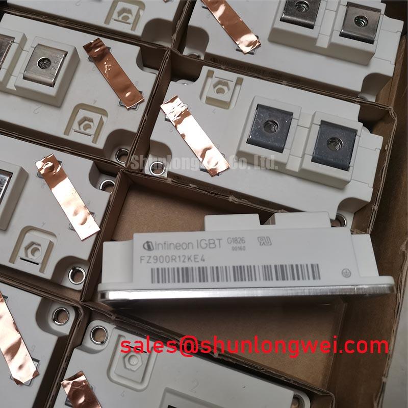
During procurement comparison, the FF650R17IE4DP_B2 can serve as a separate catalog reference, not an assumed drop-in replacement. Compare documented topology, current-rating conditions, terminal positions, footprint, driver requirements, and thermal performance. For the FZ1800R17KF6C_B2, retain the complete designation when matching the module to the original equipment bill of materials.
Optocoupler vs Digital Coreless Transformer Isolation in High-Voltage Switching
Inspect the installed gate-driver assembly before deciding whether its isolation technology is relevant to the fault. The module's 1700 V rating does not specify the isolation performance of an external driver. Identify the actual isolator, isolated power supply, connector arrangement, and PCB insulation barriers from the PCS documentation. An optocoupler-based board and a coreless-transformer-based board are not interchangeable solely because their control interfaces appear similar.
Design Consideration: Evaluate propagation delay, channel matching, common-mode transient immunity, fault communication, and startup behavior under the driver's stated conditions. A transient withstand test value is not equivalent to a permissible continuous working voltage. Reinforced-isolation claims require supporting component documentation and assessment of the complete insulation arrangement; they cannot be inferred from the isolation technology's name.
For intermittent unwanted switching, correlate the controller command, isolated driver output, local supply, and measured gate voltage. Use equipment suitable for the working voltage and measurement location. Check whether the disturbance occurs during switching transitions, supply startup, or fault recovery. These observations help separate a control-command problem from driver-supply instability, common-mode coupling, or a gate-loop issue without assigning one cause prematurely.
Inspect barrier regions for contamination, damaged connectors, and wiring that bridges intended separation. Creepage and clearance requirements depend on working voltage, insulation classification, pollution conditions, and the applicable equipment standard. Preserve the approved PCB layout and wiring arrangement rather than applying an arbitrary spacing rule during field repair.
Infineon's Reverse Conducting IGBT application note provides manufacturer discussion of reverse-conducting IGBT behavior. Its scope should remain separate from this product's identity: the document does not, by itself, establish that the FZ1800R17KF6C_B2 uses that architecture. Use the model-specific equivalent circuit and characteristics when assessing reverse-current paths in a bidirectional PCS.
After repair, validate driver fault reporting and recovery through the equipment's approved commissioning procedure. Isolation-component specifications also do not establish whole-system EMC compliance. Switching-related disturbances must be evaluated at the PCS level, with its actual enclosure, grounding, cables, and filters.
Dynamic Power Loss Dissipation and Multi-RC Thermal Ladder Representation
Investigate an overtemperature trip by checking cooling performance and installation condition before attributing it to module wear. Inspect the applicable air or liquid cooling path, heatsink cleanliness, sensor attachment, interface condition, and mounting integrity. Compare temperature behavior with operating current, switching activity, and ambient conditions. A case-temperature reading alone does not establish the semiconductor junction temperature.
Design Consideration: Conduction loss depends on the device's on-state characteristic and current waveform; switching loss depends on operating voltage, current, gate conditions, and switching frequency. Reverse-current losses must follow the documented circuit and device characteristics. Use the FZ1800R17KF6C_B2's own curves and test conditions rather than scaling another module's losses by rated current.
A transient thermal assessment requires the manufacturer's junction-to-case thermal impedance data. For a rectangular loss pulse under the model's stated assumptions, the temperature rise can be estimated from pulse power multiplied by the corresponding transient thermal impedance. Repeated pulses require accounting for accumulated heating and the case-temperature boundary. This is an Engineering Calculation method, not a temperature guarantee inferred from the nameplate ratings.
When thermal-model coefficients are available, establish whether they describe a Foster network or a Cauer ladder before connecting the model to a heatsink representation. Their network structures are not interchangeable without the appropriate transformation. Avoid inventing RC coefficients when only a plotted curve is available; use a documented model or a justified curve-based assessment with its limitations recorded.
For practical test and failure-analysis context, the Field Engineer’s Handbook complements the equipment service procedure. Keep repair records focused on measured conditions, protection events, installation details, and test results rather than unsupported lifetime estimates.
Before returning the PCS to service, compare measured case temperature and calculated junction-temperature excursions against the module's documented operating limits throughout the approved commissioning sequence. If thermal margin is inadequate, review cooling, interface installation, switching conditions, and load profile with the system engineer; the 1800 A rating alone does not authorize continuous operation at that current in the repaired assembly.