Content last revised on October 20, 2026
FF800R17KF6C-B2 Thermal-Electrical Optimization: Auxiliary Emitter Pinout Cold-Check Practical Tuning
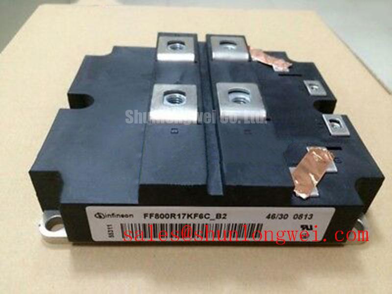
I trace the driver return against the terminal drawing before measuring the disconnected gate circuit. For the FF800R17KF6C-B2, terminal identification must come from its specific connection diagram, not the position of a connector on a similar module. Where the drawing identifies an auxiliary emitter connection, distinguish that signal return from the main emitter connection carrying load current. A continuity reading alone cannot establish the intended role of a terminal.
Design Consideration: Shared emitter inductance can introduce a voltage disturbance into the gate drive reference as load current changes. Keep the outgoing gate path and its designated return closely coupled, and avoid routing the driver reference through a main current connection. The objective is to reduce coupling between the power circuit and the control loop; conductor spacing and clearance remain subject to the assembly insulation design and mechanical constraints.
With the assembly safely discharged and the driver disconnected as required by the service procedure, compare gate path resistance and continuity with the schematic. Account for external resistors, protection components, and parallel paths before interpreting a reading. An unusual measurement should prompt isolation of the relevant circuit section rather than an immediate conclusion about the module.
During controlled switching measurements, reference the gate waveform to the designated emitter return using a suitably rated measurement arrangement. Compare switching edges with disturbances on the inactive gate. Ringing or an apparent gate excursion can involve probe pickup, shared return impedance, or driver behavior; changing the measurement arrangement helps separate these effects before changing components.
For replacement assessment, compare the FF800R17KF6C-B2 against the equipment bill of materials and service drawing. The FF1000R17IE4 is a separate comparison candidate, not an automatic substitute. Terminal arrangement, mounting geometry, switching characteristics, thermal requirements, and protection compatibility must support any substitution decision. Engineers evaluating a multi-megawatt offshore or onshore wind turbine full-scale converter should make that comparison at the converter assembly level.
Assembly Integrity & Layout Architecture: Implementing Galvanic Gate Drive Isolation, Reinforced for FF800R17KF6C-B2
Trace the isolation barrier from the controller interface through the driver and its isolated supply before evaluating switching performance. An isolated signal channel does not establish reinforced insulation for the complete board. Connector spacing, supply transformer construction, board contamination, and the applicable equipment requirements all affect the assessment.
Design Consideration: Select the insulation classification and common-mode transient immunity of the gate driver for the actual working voltage and measured switching environment. An isolation test voltage is not an allowable continuous working voltage, and neither is a rating of the IGBT module simply because the driver is connected to it. The Infineon EiceDRIVER gate driver portfolio provides manufacturer information for comparing driver functions; device-specific documentation remains necessary for the selected circuit.
Source and sink capability should be evaluated against the gate charging demand, commanded transition time, and total gate loop impedance. External gate resistance influences ringing, switching loss, and voltage overshoot together. Adjusting resistance to clean up a waveform without checking temperature and collector voltage can move the problem elsewhere. Use controlled switching tests to establish the damping appropriate to the assembled power stage rather than transferring a resistor value from another module.
Inspect the local driver supply during switching as well as at idle. Supply droop can change gate amplitude or activate undervoltage protection even when the controller command is correct. Where the existing driver uses a bootstrap supply, assess capacitor recharge opportunity, charging path losses, and diode reverse recovery against its switching sequence. This is a driver architecture consideration, not an identified feature of the FF800R17KF6C-B2.
Route sensitive control connections away from switching nodes and maintain the approved barrier clearances after harness installation. Cable movement, contamination, or an incorrectly positioned mounting accessory can compromise an otherwise acceptable board layout. When investigating spurious commands, correlate the input signal, isolated output, supply voltage, and gate waveform before attributing the disturbance to common-mode susceptibility.
Assembly Integrity & Layout Architecture: Implementing High-Speed Fault Management: VCE Desaturation for FF800R17KF6C-B2
Review the desaturation sensing path and its timing before enabling the power stage after a repair. A protection circuit must distinguish normal collector voltage during switching from a sustained abnormal condition while leaving sufficient time for fault recognition and controlled shutdown.
Design Consideration: Check the complete protection delay, including sensing, filtering, driver response, and current decay, against the module’s documented short-circuit conditions. A generic response-time target does not establish protection compatibility. A fault present at turn-on and a fault developing during conduction place different demands on the detection path, so the validation plan should address both conditions through an approved, current-limited test method.
Inspect the desaturation diode path, local connections, and their separation from the gate loop. Excessive filtering can delay detection, while insufficient rejection of switching transients can cause nuisance trips. Compare the sense waveform with the gate command and collector voltage using appropriately rated instrumentation. A repeated trip is evidence to investigate, not proof that the power module alone is defective.
A staged or soft shutdown strategy can reduce the rate of fault current interruption and the associated inductive voltage rise. Its suitability depends on the driver implementation and the module’s documented operating boundaries. The shutdown must balance voltage overshoot against continued fault energy; timing and gate discharge behavior should be established for the actual assembly rather than assigned as universal settings.
Confirm that a protection event inhibits subsequent commands and reports a latched fault in accordance with the equipment control scheme. Check startup, loss of driver supply, and reset behavior as separate cases. The Infineon IGBT Modules & Discretes Official Portfolio is an appropriate manufacturer reference for device documentation, but portfolio information should not be substituted for this model’s protection limits.
FF800R17KF6C-B2 Circuit Protection & Reliability: Calibrating Baseplate Isolation Breakdown Testing
Select the approved insulation test procedure before connecting an insulation tester between power terminals and the baseplate. Insulation resistance measurement and dielectric withstand testing serve different purposes; neither should be improvised from the module’s rated blocking voltage.
Design Consideration: Use the specified terminal grouping, test voltage, duration, environmental conditions, and acceptance criteria from the applicable module and equipment procedures. Disconnect sensitive electronics where those procedures require it. A test applied across an unintended path can stress attached driver circuitry and produce a misleading result. Record the instrument identification, connection arrangement, temperature, and humidity so later measurements remain comparable.
A satisfactory insulation resistance result does not, by itself, establish the integrity of every internal insulating structure. Surface contamination, moisture, and connected circuitry can influence a reading. Investigate an unexpected change by checking the external leakage path and test setup before making a judgment about internal damage. Keep creepage surfaces clean using approved materials, and allow equipment exposed to condensation to reach the required dry condition before testing or energization.
At planned service access, inspect heatsink airflow, dust accumulation, mounting condition, and accessible evidence of thermal interface deterioration. Set inspection intervals from equipment duty and recorded temperature trends rather than an invented module service life. Check terminal fastening with the specified procedure and calibrated tools; repeated tightening without a defined method is not a substitute for connection assessment.
Maintenance Note: Trend terminal temperature rise under comparable load conditions and inspect cooling airflow before returning a serviced assembly to routine operation.
For broader technology comparisons, the distributor’s Wide Bandgap Revolution article provides context on GaN and SiC integration challenges, not FF800R17KF6C-B2 test authority. Keep this module’s maintenance record focused on measured insulation behavior, connection condition, cooling performance, and documented corrective work, with abnormal trends assigned a specific inspection or retest action.