


Content last revised on July 15, 2026
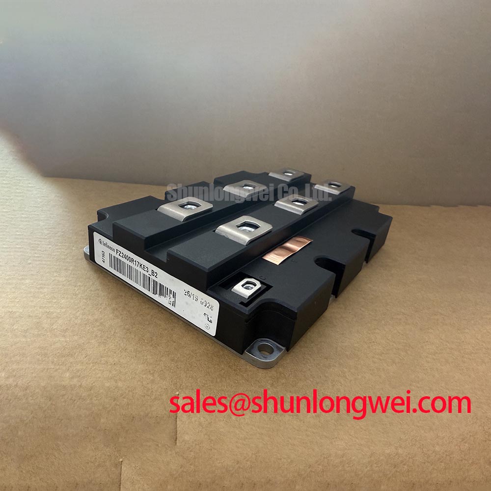
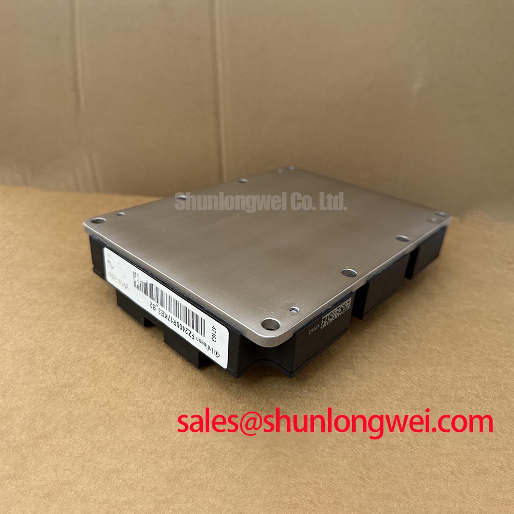
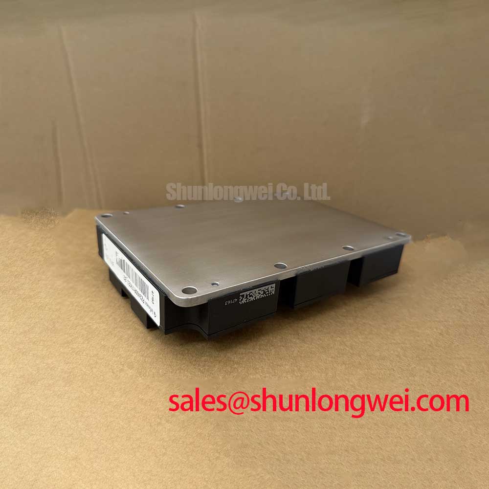
FZ2400R17KE3_B2 Infineon 1700V 2400A IGBT Module: High-Power Density for Grid-Scale Conversion
The Infineon FZ2400R17KE3_B2 represents a benchmark in high-power semiconductor engineering, specifically designed to address the rigorous demands of multi-megawatt power conversion systems. As a single-switch IGBT module utilizing TRENCHSTOP™ IGBT3 technology, it offers a decisive 1700V blocking voltage and a 2400A continuous collector current rating. This module is primarily valued for its exceptional thermal stability and high current density, enabling engineers to reduce the footprint of high-power stacks. For systems prioritizing thermal margin and ruggedness under short-circuit conditions, this 1700V module stands as the optimal choice for modern industrial infrastructure.
Top Specs: 1700V Collector-Emitter Voltage | 2400A Continuous DC Collector Current | 10µs Short Circuit Withstand Time.
Key Benefits: Maximized power density for compact inverter designs and enhanced reliability through advanced trench/fieldstop chip architecture. A common question engineers ask is how the Vce(sat) profile affects long-term efficiency; the FZ2400R17KE3_B2 maintains a low typical saturation voltage, which significantly curtails conduction losses in high-duty-cycle applications.
Application Scenarios & Value
Achieving System-Level Benefits in High-Frequency Power Conversion
Engineers often face the challenge of managing immense thermal loads in confined spaces, such as wind turbine nacelles or utility-scale Solar Inverters. In a typical grid-scale energy storage system (BESS), the FZ2400R17KE3_B2 serves as the primary switching element in the power conversion stage. By handling 2400A in a single IHM-B package, engineers can often reduce the number of paralleled modules required for a 2MW inverter. This reduction in component count directly lowers the complexity of the Gate Drive circuitry and simplifies the mechanical busbar layout.
Consider a heavy industrial Variable Frequency Drive (VFD) operating a 1.5MW motor. The startup surge currents can stress lower-rated components, leading to premature thermal fatigue. The FZ2400R17KE3_B2, with its high Ices ruggedness and 10µs short-circuit withstand time, provides a critical safety buffer that prevents catastrophic failure during unexpected load transients. In systems requiring even higher power handling for 690V line applications, the related FZ3600R17KE3_B2 offers an increased current capability of 3600A while maintaining the same 1700V platform.
For designers working on 1200V-based systems who require high-speed switching performance, the related FZ2400R12HP4 provides a lower voltage alternative with optimized switching losses. You can explore more technical nuances in our Engineering Guide to IGBT Modules.
Technical & Design Deep Dive
A Closer Look at Trenchstop IGBT3 Technology for Long-Term Reliability
The core of the FZ2400R17KE3_B2 is the TRENCHSTOP™ IGBT3 chip. To understand its efficiency, one can use the analogy of a hydraulic valve: a standard valve might have internal friction that slows down flow and generates heat (conduction loss). The Trenchstop architecture acts like a precision-polished valve with a wider aperture, ensuring that even at massive flow rates (2400A), the internal resistance remains minimal. This results in a low Vce(sat), ensuring that more energy reaches the grid rather than being dissipated as waste heat.
From a thermal perspective, the FZ2400R17KE3_B2 utilizes a high-performance AlSiC baseplate which matches the thermal expansion coefficient of the internal ceramic substrates. This is critical for Power Cycling Capability. Think of the Thermal Resistance (Rth) as a bridge over a river. If the bridge is narrow, traffic (heat) bottlenecks and the temperature on one side spikes. The FZ2400R17KE3_B2 provides a "wide bridge" design, ensuring heat moves efficiently from the junction to the heatsink, thereby preventing localized hotspots that cause silicon degradation. This mechanical robustness is essential for applications like Electric Vehicle (EV) Inverter testing stations or railway traction converters where load cycles are frequent and aggressive.
Key Parameter Overview
Decoding the Specs for Enhanced Thermal Reliability
The following parameters are extracted from the official Infineon technical documentation to assist in your hardware validation process.
| Parameter Symbol | Technical Specification | Engineering Significance |
|---|---|---|
| Vces | 1700V | Maximum blocking voltage for 690V AC line systems. |
| Ic (nom) | 2400A | Continuous current handling at Tc=80°C. |
| Vce(sat) | 2.00V (typ) | Low conduction loss profile at rated current. |
| tsc | 10µs | Short-circuit withstand time for protection coordination. |
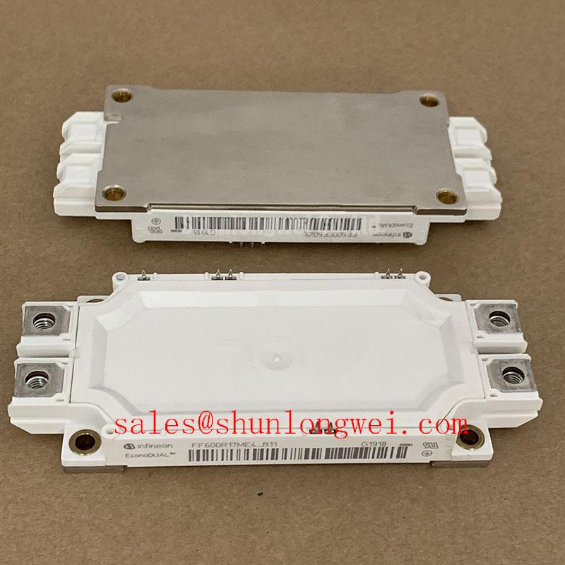
| Package | IHM-B | Standardized high-power footprint for industrial integration. |
Download the FZ2400R17KE3_B2 datasheet for detailed specifications and performance curves.
FAQ
What are the cooling requirements for the FZ2400R17KE3_B2 at full rated current?
Due to the 2400A rating, liquid cooling is typically mandatory. The low Thermal Resistance of the module ensures efficient heat transfer, but the external cold plate must be designed to handle several kilowatts of dissipation to maintain the junction temperature below the 125°C or 150°C limits specified in the datasheet.
How does the 1700V rating benefit 690V industrial applications?
In 690V AC systems, the DC link voltage often reaches 1100V. A 1700V IGBT provides a critical voltage margin (Safety Operating Area) to account for inductive voltage spikes during switching transients, reducing the need for oversized Snubber Circuits.
Does this module support parallel operation for multi-megawatt stacks?
Yes, the FZ2400R17KE3_B2 features a positive temperature coefficient for Vce(sat), which naturally assists in current sharing when multiple modules are paralleled. However, symmetrical Gate Drive routing and busbar design are still required to ensure balanced performance.
Is the B2 package variation compatible with standard IHM-B mounting?
The B2 suffix generally indicates a specific internal diode configuration or terminal arrangement within the IHM-B family. Designers should verify the mechanical drawing in the official datasheet to ensure busbar alignment and clearance distances meet IEC standards.
Strategically, adopting the FZ2400R17KE3_B2 allows manufacturers to standardize their power blocks for the next generation of high-efficiency energy systems. As the industry shifts toward 1500V DC bus architectures, the voltage overhead provided by 1700V silicon becomes a prerequisite for operational longevity. For technical insights into maintaining these high-power modules, refer to our guide on Field Testing and Reliability.