Content last revised on October 3, 2026
FZ400R65KF1 Gate Return Checks and Circuit Protection
| Model | Manufacturer | Product category | Package | Rated voltage | Rated current |
|---|---|---|---|---|---|
| FZ400R65KF1 | Infineon | IGBT module | Module | 6500 V (Official Specification) | 400 A (Official Specification) |
With the DC link isolated and discharged, measure the cold resistance between the gate and emitter connections, then compare it with the removed module and the equipment schematic. Check the gate connector, its return conductor and nearby power terminals for looseness or heat discoloration. A resistance reading alone cannot clear the gate drive: an intermittent return path may only become apparent during switching.
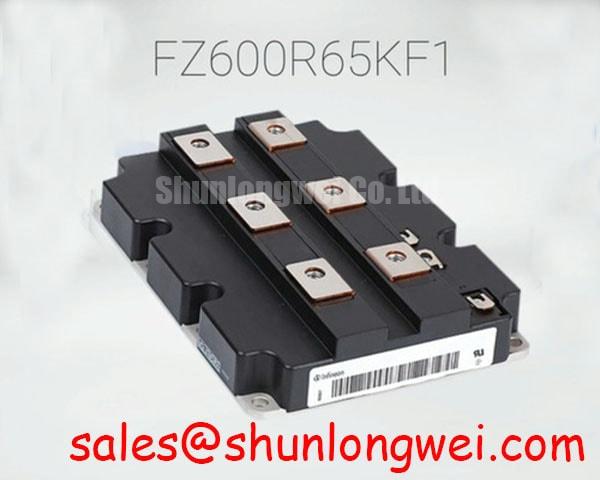
The FZ400R65KF1 is an Infineon IGBT module rated at 6500 V and 400 A (Official Specifications). Those ratings establish component boundaries, not a gate-pin assignment. Identify every gate and emitter terminal from the module documentation before treating any connection as an auxiliary Kelvin emitter. If a separate emitter-sense connection is documented, route its driver return independently of the high-current emitter path. This is a Design Consideration intended to reduce the effect of power-path voltage on the gate signal; the required routing and clearances remain system-dependent.
Probe gate-to-emitter voltage at the driver reference during a controlled switching test. If the waveform differs from the command signal, inspect the return connection and compare it with a known-good channel before changing gate components. Keep the measurement loop short so the probe does not introduce a misleading spike. Infineon’s IGBT module portfolio provides broader device context, but the terminal drawing for this exact module must govern the connection check.
FZ400R65KF1 Current Sharing and Gate Interlock Checks
Capture the gate commands and current waveforms of any parallel devices during a controlled load test; a cold resistance match does not establish dynamic current balance. Inspect gate wiring for unequal path lengths, connector condition and differences in driver return routing. Static sharing also depends on device characteristics and temperature. Treat a positive temperature coefficient of saturation voltage as a possible design aid only after verifying its applicable operating range in the relevant device data, rather than assuming it guarantees sharing for this installation.
At each complementary switching transition, check the command signals and measured gate-to-emitter waveforms for overlap. Dead time must account for driver propagation, device turn-off and operating variation; the system designer should establish it from the actual drive chain and switching tests. If a shoot-through alarm appears, inspect interlock wiring and timing alongside the power stage instead of assigning the fault to the module from the alarm alone.
A replacement decision requires the original circuit position, terminal arrangement, voltage boundary, current duty, gate drive and cooling interface to agree. The FZ800R12KS4_B2 is another module a repair team may encounter in a parts review, but its different model designation is not evidence of interchangeability with the FZ400R65KF1. Likewise, a topology drawing may identify an FZ3600R12HP4 elsewhere in the equipment; verify that stage’s function and ratings separately rather than treating it as a drop-in device.
FZ400R65KF1 Hard-Switching Transients and Fault Turn-Off
Record collector-to-emitter voltage and gate-to-emitter voltage through a controlled turn-off event, looking for overshoot, ringing or unintended gate rise. Compare the traces with a known-good channel under comparable conditions. Minimize the commutation-loop inductance to limit turn-off overshoot, then verify the measured peak against the module’s 6500 V rating (Official Specification) and the system’s operating limits. Clearance and routing choices must follow the equipment insulation design; the voltage rating alone does not set a layout rule.
Check whether the driver detects a short-circuit condition and how it turns the gate off after detection. Detection delay, blanking and any staged soft turn-off must be evaluated against the module’s applicable short-circuit limits and the complete drive circuit. No fixed detection time or turn-off profile can be inferred from the stated voltage and current ratings. A staged turn-off can reduce an abrupt current interruption, but its suitability depends on measured fault waveforms and the equipment protection scheme.
Miller coupling is another waveform check: a collector voltage transition can disturb the gate through the device’s transfer capacitance. Inspect the off-state gate trace before considering an active clamp or a driver change. If the circuit contains a freewheel diode, its recovery behavior also belongs in the switching assessment; confirm the installed diode configuration and measure its effect rather than assigning a recovery characteristic to this module without device data. Infineon’s IGBT switching application note discusses relevant mechanisms, although its device examples must not be treated as FZ400R65KF1 specifications.
Field alert: Discharge and verify the DC link before touching module terminals or disconnecting the gate harness.
FZ400R65KF1 Operating Boundaries in Central Solar Inverters
Read the inverter’s DC-link operating record and fault log before evaluating the module for a central solar inverter repair. A utility-scale 1500 V photovoltaic system is a possible compatibility assessment, not a defined application or operating limit for this part. The engineer must match the actual circuit topology, transient voltage, current waveform, thermal path and protection behavior to the module documentation. Its 6500 V and 400 A ratings (Official Specifications) cannot, by themselves, establish that fit.
Inspect mounting contact, cooling hardware and thermal-interface coverage when a channel shows repeated temperature-related trips. Compare measured case temperatures and load history across equivalent positions. For pulsed operation, junction-temperature assessment requires the applicable transient thermal-impedance data and the real power waveform; a continuous current rating is not a substitute. In systems with repeated charge and discharge cycles, review those thermal swings as part of the equipment-level duty assessment without inferring a service life from them.
At an elevated-altitude installation, record the site conditions and DC-link voltage before making a reliability claim. Neutron-related single-event burnout and failures-in-time estimates require device-specific reliability evidence and a defined operating environment. The ratings provided here support neither a numerical FIT calculation nor an altitude derating. For a wider equipment-level troubleshooting context, the industrial applications guide can inform the review; the repair decision should rest on this module’s documented limits and measurements from the installed system.