Content last revised on September 10, 2026
High-Voltage Power Conversion with FZ600R65KE3
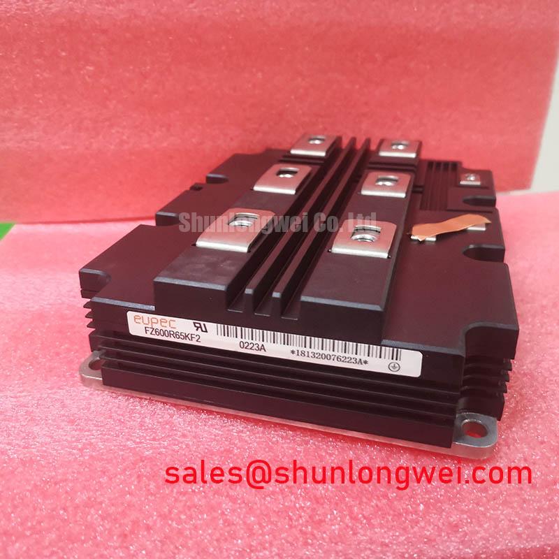
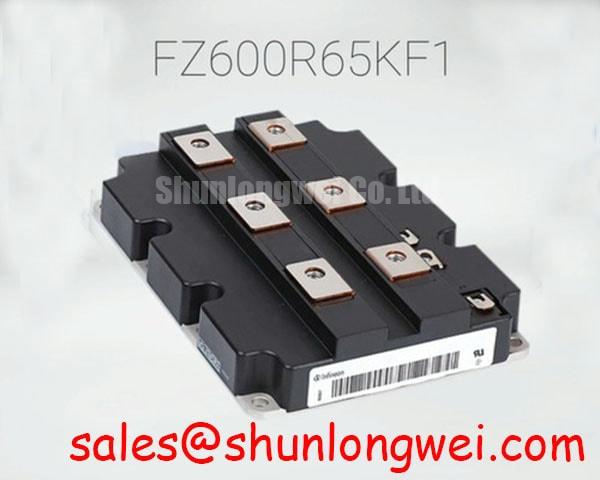
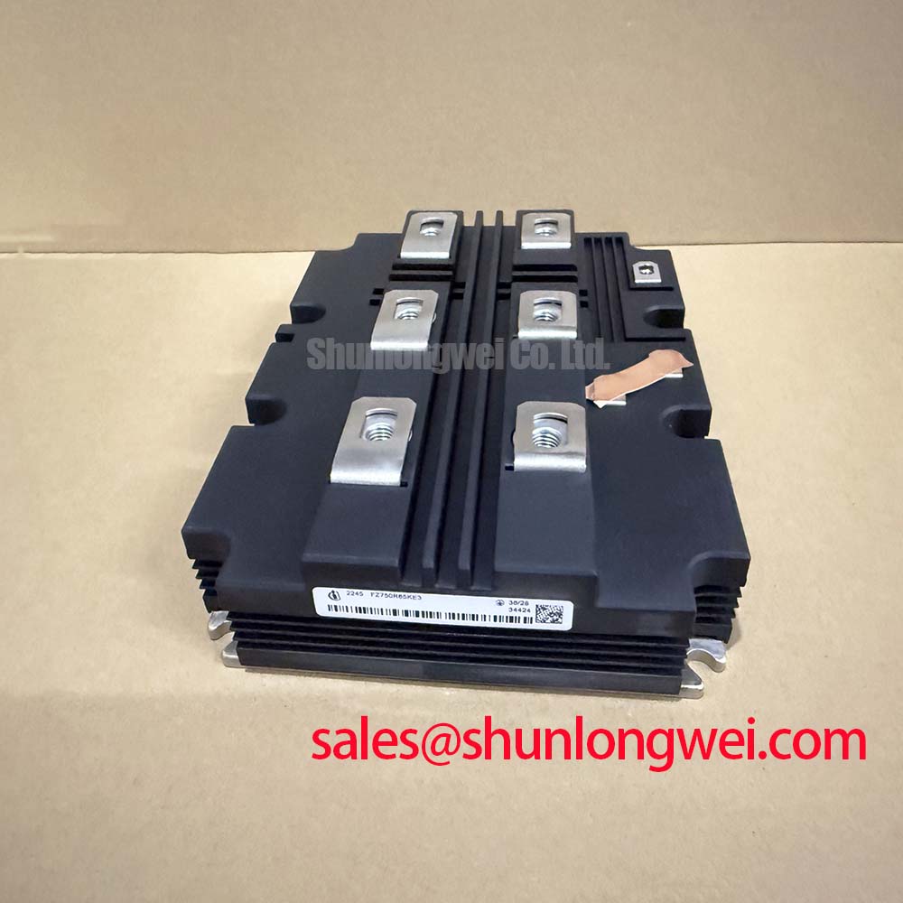
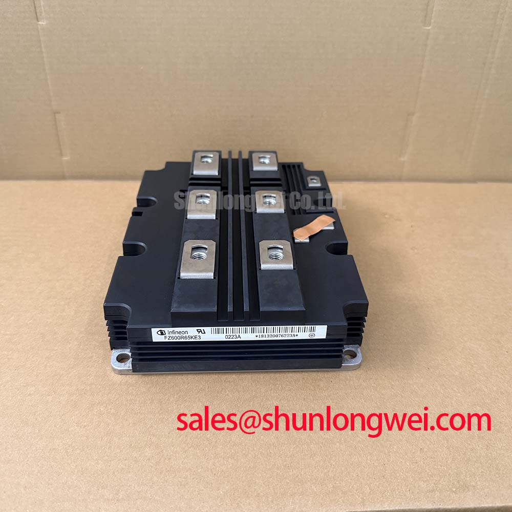
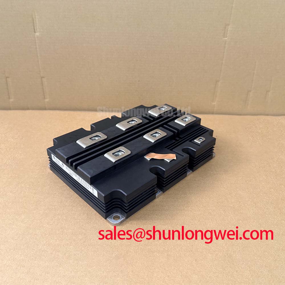
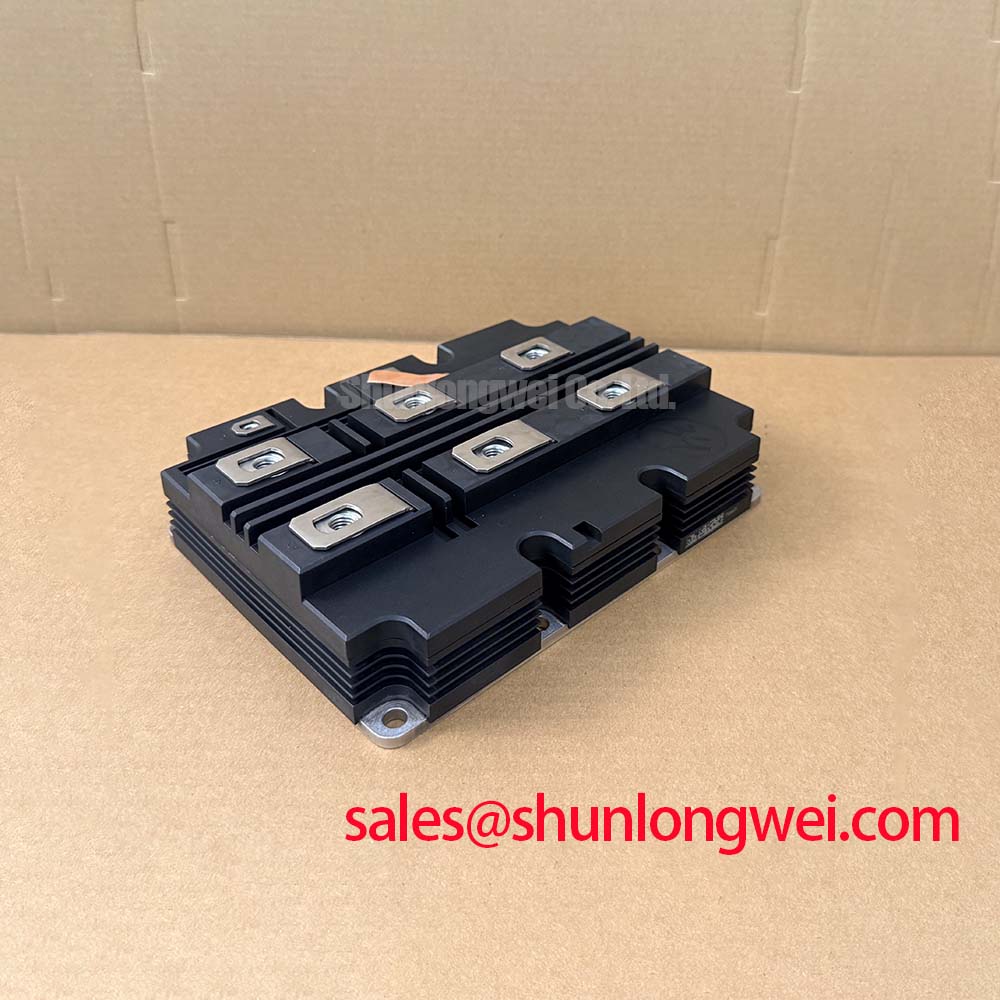
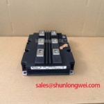
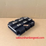
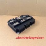
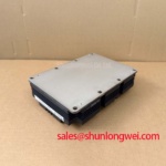
The FZ600R65KE3 is a high-power single switch IGBT Module developed by Infineon. Engineered for traction drives and medium-voltage converters, this module provides highly insulated performance under extreme electrical and thermal stresses.
- UVP Statement: Delivering traction-grade 10.4kV AC insulation and AlSiC thermal cycling endurance for medium-voltage grids and heavy industrial converters.
- Top Specs: 6500V | 600A | 10.4kV AC isolation voltage.
- Key Benefits:
- AlSiC baseplate improves thermal cycling lifetime under varying load demands.
- Package tracking index (CTI > 600) prevents high-voltage breakdown in polluted environments.
- Core Question Answered: How does the AlSiC baseplate prevent package degradation? By matching the thermal expansion coefficient of the silicon die, it prevents solder fatigue during temperature swings.
Application Scenarios & Value
Mitigating Thermal and Electrical Stress in Medium-Voltage Networks
For traction converters and medium-voltage drives prioritizing high-voltage isolation and thermal cycling lifespan, the FZ600R65KE3 is the optimal choice.
Engineers often face the severe challenge of designing power electronic converters for high-altitude rail transit and medium-voltage grid hubs, where thermal stress and insulation breakdown pose constant risks. The 6500V collector-emitter voltage (VCES) rating of this module directly addresses these issues, providing ample safety headroom for grid fluctuations. Operating in traction converters requires coping with high-current surges during acceleration. The 1200A repetitive peak collector current (ICRM) ensures the system remains within its safe operating area without risking degradation.
Furthermore, when performing failure analysis and reliability assessments, engineers must ensure the isolation coordination matches the system topology. The 10.4kV AC isolation test voltage simplifies design compliance with international rail standards. While this module is ideal for medium-voltage grid applications, systems operating at lower distribution voltages may utilize the related FZ600R17KE3 which offers a 1700V rating.
Technical & Design Deep Dive
A Closer Look at the AlSiC Baseplate and Insulation for Long-Term Reliability
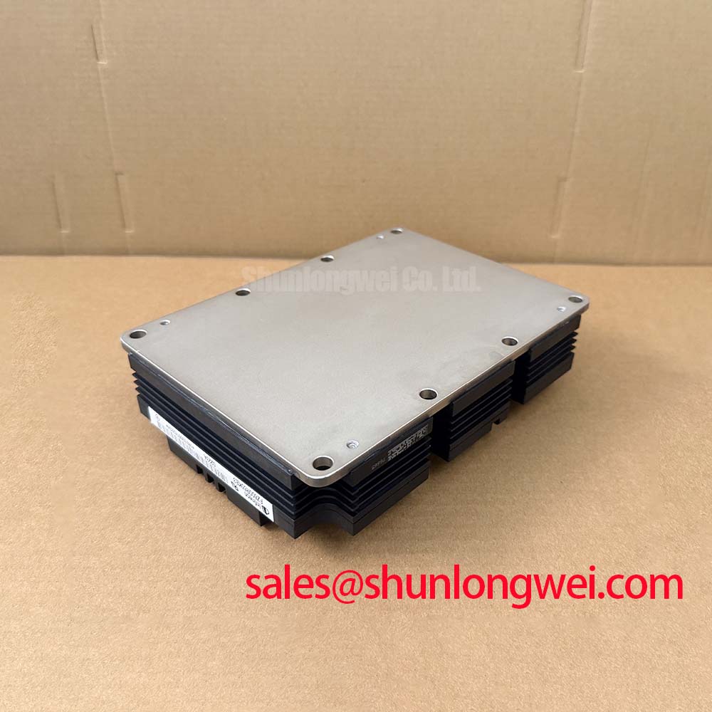
The physical structure of the FZ600R65KE3 is optimized to manage thermal expansion. Standard copper baseplates expand at a much higher rate than the internal ceramic substrate, leading to solder delamination over thousands of power cycles. By using an Aluminum Silicon Carbide (AlSiC) baseplate, Infineon matches the thermal expansion rates, which extends the module's operating lifetime.
To visualize this thermal pathway, think of the AlSiC baseplate as a superhighway for heat. Just as a wider highway prevents traffic jams, the low thermal resistance (RthJC) of 10.2 K/kW (0.0102 K/W) per IGBT allows heat to escape the silicon die almost instantly, preventing localized hotspots from stalling the system. What is the primary benefit of the AlSiC baseplate? It matches thermal expansion coefficients to eliminate solder joint fatigue. Why does the module have a CTI over 600? To prevent tracking and breakdown in highly polluted or humid environments.
Similarly, the module's creepage distance of 64.0 mm acts like a wide firewall. Just as a fire cannot jump across a vast barren trench, high-voltage leakage currents are prevented from bridging the gap to the heatsink. This design relies on the Infineon TRENCHSTOP™ IGBT3 technology. It provides a lower collector-emitter saturation voltage (VCE(sat)) of 3.00V typical at 25°C, reducing conduction losses during steady-state operation. Integrating these modules requires careful layout optimization to keep stray inductance within the module's rated 18 nH limit, protecting the gates from high-voltage spikes during turn-off.
For detailed information on system integration, refer to our guide on thermal management and gate drive topologies.
Key Parameter Overview
Decoding the Specs for Enhanced Thermal Reliability
The following table lists the critical electrical and mechanical specifications of the FZ600R65KE3. Highlighting these values assists engineers during the initial phase of component selection.
| Parameter | Symbol | Typical / Rated Value | Unit |
|---|---|---|---|
| Collector-Emitter Voltage | VCES | 6500 | V |
| Continuous DC Collector Current | IC | 600 | A |
| Repetitive Peak Collector Current | ICRM | 1200 | A |
| Isolation Test Voltage (RMS, f=50 Hz, t=60 s) | VISOL | 10.4 | kV |
| Collector-Emitter Saturation Voltage (Tvj=25°C, IC=600A) | VCE(sat) | 3.00 | V |
| Collector-Emitter Saturation Voltage (Tvj=125°C, IC=600A) | VCE(sat) | 3.70 | V |
| Thermal Resistance, Junction to Case (per IGBT) | RthJC | 10.2 | K/kW (0.0102 K/W) |
| Comparative Tracking Index | CTI | > 600 | — |
| Stray Inductance Module | LsCE | 18 | nH |
Download the FZ600R65KE3 datasheet for detailed specifications and performance curves.
Frequently Asked Questions
Addressing Common Engineering Design Queries
How does the positive temperature coefficient of VCE(sat) affect paralleling?
The saturation voltage increases from 3.00V at 25°C to 3.70V at 125°C. This positive temperature coefficient naturally balances current sharing when paralleling multiple modules, preventing thermal runaway in high-power configurations.
Why is the 10.4kV AC isolation rating critical for grid-tied converters?
A high isolation rating of 10.4kV AC allows the module to operate safely in series configurations or directly on medium-voltage grids without requiring excessive external isolation barriers.
What design parameters are critical to mitigate the effects of the module's 18 nH stray inductance?
To prevent overvoltage spikes during switching, engineers should utilize low-induction DC-link busbars, optimize snubber circuits, and implement active clamping in the gate driver circuitry.
As industrial systems transition toward higher grid integration and electrification, power stage design dictates system longevity. Selecting a highly insulated IGBT module like the FZ600R65KE3 provides the electrical and mechanical margins required to withstand decades of field operation.