

Content last revised on September 14, 2026
G150XTN03.2 Incoming Inspection and Integration Notes
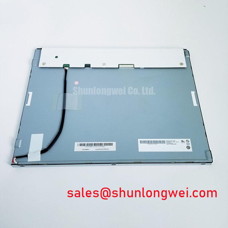
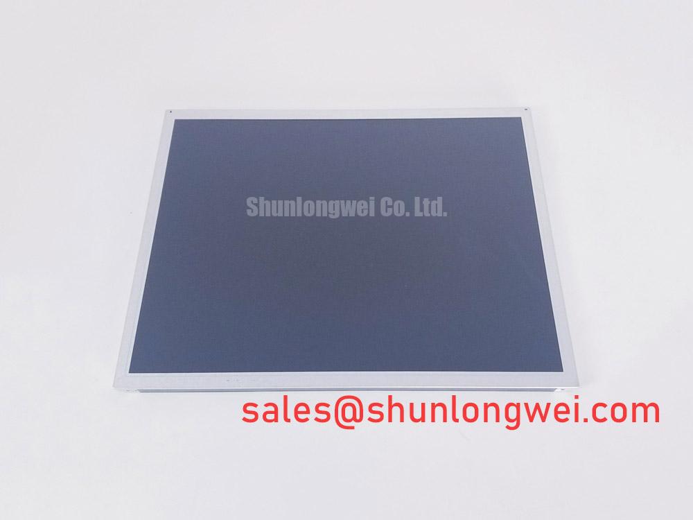
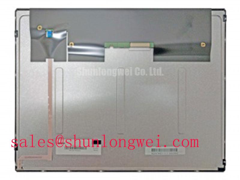
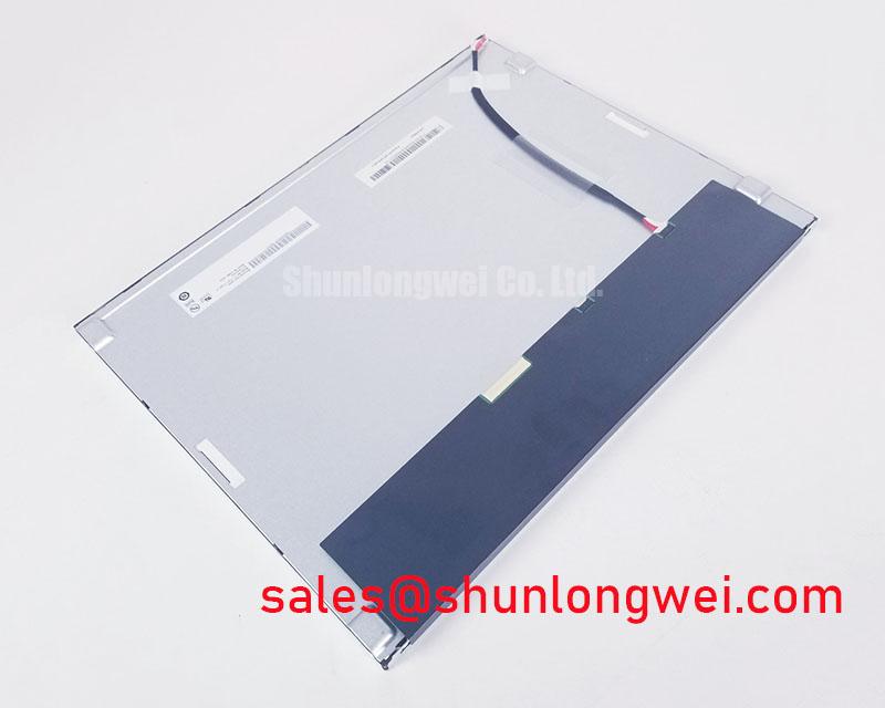
Begin the incoming inspection by comparing the nameplate and connector arrangement of the replacement against the removed panel, then check the glass, bezel, flex connections, and mounting points for visible damage before applying power. The G150XTN03.2 is an AUO TFT LCD Display Module classified for industrial LCD and HMI panel applications. The supplied factory context identifies the product category and manufacturer, but it does not confirm a numerical resolution, active-area dimension, interface voltage, backlight type, luminance value, viewing angle, or connector pinout. Those items should be verified from the original panel documentation before system integration.
| Model | G150XTN03.2 |
| Manufacturer | AUO |
| Product category | Industrial Grade LCD/HMI Panel |
| Construction designation | TFT-LCD Display Module |
| Specification status | Detailed specifications require verification from the applicable documentation |
For a repair engineer, the most important first decision is physical and electrical compatibility rather than a general screen-size match. Confirm the mounting-hole pattern, bezel opening, panel thickness, optical direction, cable exit position, and controller-board clearance. The system integrator should verify the required supply voltage from the original panel documentation. The same caution applies to the image interface, backlight supply, enable signal, brightness control, and power-sequencing requirements.
Optical Luminance Degradation Curve and CCFL-to-LED Modernization Retrofit Pathways
Do not assume that a replacement panel can accept the backlight wiring used by the original display. The available factory context for G150XTN03.2 does not confirm whether the specific unit is supplied with a CCFL or LED backlight, nor does it provide a luminance-degradation curve or an approved retrofit procedure. If the existing equipment uses a high-voltage fluorescent backlight, its inverter, ignition behavior, shutdown timing, and fault detection must be assessed separately from the LCD signal path.
When evaluating an LED modernization route, the engineer should treat the constant-current driver as a system-level interface. Confirm the driver’s output range, current regulation behavior, enable polarity, dimming method, thermal operating conditions, and protection response against the original panel documentation. PWM frequency and duty-cycle linearity should be selected through system testing to avoid visible flicker, control noise, or unstable brightness. A claimed operating life or half-brightness period must come from the applicable backlight datasheet or qualification report; it should not be inferred from the AUO model designation.
For a harsh marine radar or navigation bridge console, optical evaluation should include the actual cover glass, anti-glare treatment, enclosure shading, and ambient-light conditions. Salt exposure and condensation control belong to the enclosure design and are not automatically covered by the display module specification. A retrofit should therefore be approved only after checking image visibility, backlight thermal behavior, mechanical fit, and the host system’s alarm and dimming functions.
Eye-Diagram Voltage Margin and Differential Noise-Floor Verification in High-Vibration Bays
Inspect the signal cable path before investigating image artifacts. Confirm that the replacement cable has the same connector keying, contact count, orientation, shielding arrangement, and termination as the original assembly. The supplied information does not confirm whether G150XTN03.2 uses LVDS, TTL, or another interface, so the interface type and data format must be taken from the original panel documentation rather than assumed from the product category.
Where the host system uses a differential display link, verify the required JEIDA or VESA data mapping, pixel-clock polarity, lane order, and power-up sequence. Differential pairs should be routed as a controlled, balanced signal path with minimized loop area and consistent reference return. The final cable and PCB design should be validated with the known-good panel installed, using oscilloscope measurements to compare eye opening, common-mode behavior, clock stability, and intermittent noise during motor-drive or relay switching events.
In a high-vibration equipment bay, strain relief is as important as electrical screening. Prevent the FFC or LVDS cable from carrying connector load, and keep the cable clear of fan edges, hinges, sharp chassis features, and high-current switching loops. A 360-degree shield termination may be suitable for a particular enclosure, but its grounding method must be checked against the host system’s bonding and EMC design. Ferrite suppression can alter signal integrity, so any added component should be verified against the actual data rate and cable construction.
💡 Pro Tip: Keep the display cable’s differential routing symmetrical and separate from switching power conductors, then confirm the result with the known-good signal path before changing termination or filtering.
For cross-reference work, engineers may also review LMS700KF01-001 as a separate display reference, but mechanical dimensions, interface definition, optical performance, and backlight requirements must be compared item by item rather than treated as interchangeable.
Polarizer Durability and Optical Retardation Film Inspection under Direct Industrial Lighting
Inspect the front polarizer under the lighting conditions in which the equipment will operate. Look for scratches, pressure marks, localized haze, edge lifting, uneven reflections, and contamination that could become visible when the display shows a white or dark field. These observations are useful for incoming quality control, but they do not establish the panel’s environmental qualification or long-term optical life.
Viewing-angle behavior should be measured with the installed cover, bezel, and operator position in place. The supplied factory parameters do not confirm a TN, IPS, or MVA optical mode, and they do not provide a numerical viewing-angle specification. Do not transfer viewing-cone values from another AUO panel. In a marine console, reflected sunlight, polarized eyewear, tinted windows, and protective overlays can change perceived contrast even when the display electronics are operating correctly.
Use a controlled test image to inspect grayscale transitions, solid primary colors, full white, and full black. If grayscale inversion, color shift, or a horizontal noise band appears, compare the result with the original panel and inspect the cable, controller settings, grounding, and backlight separately. This avoids assigning a single cause to a symptom that can originate in the optical stack, signal timing, power integrity, or enclosure reflections.
For broader principles covering TFT operation, panel selection, and common integration errors, consult The Ultimate Guide to Industrial TFT LCD Technology. The guide should support engineering review, while the G150XTN03.2 documentation remains the authority for model-specific limits.
Incoming Benchtop Inspection: COG and TAB Bond Integrity
Carry out the first inspection with the panel unpowered and supported on a clean, level work surface. Check the glass perimeter, flex tails, connector contacts, bonding regions, and rear surfaces for visible marks or deformation. Avoid pressing the active area or flex bonds during handling. COG and TAB construction details, bonding materials, and allowable repair limits are not confirmed in the supplied factory data, so microscopic internal failure modes should not be inferred from appearance alone.
After confirming the host controller and supply requirements, run a three-stage primary-color test using red, green, and blue screens, followed by white and black fields if supported by the test controller. Observe for fixed lines, column defects, localized dark areas, color contamination, intermittent flicker, and changes caused by cable movement. Record the result with the original panel and replacement panel under the same controller settings.
A flashlight inspection at an oblique angle can help separate a surface reflection or backlight shadow from a line defect in the active matrix. It is an observation method, not a definitive failure classification. If a line changes with cable position, connector reseating, temperature, or chassis pressure, isolate those variables one at a time and compare the signal path with a known-good assembly. Do not apply pressure to the glass or bonding area as a diagnostic action.
Bench Diagnostic: Disconnect power before inserting or removing the display cable, because live insertion can damage the panel interface or host controller.
Before release to equipment, verify the image format, backlight control, power sequencing, mounting clearance, connector retention, and final optical performance in the completed enclosure. Any marine deployment should also undergo its own sealing, condensation, vibration, and corrosion-control assessment because those system qualifications are not established by the display model designation alone.