Content last revised on October 20, 2026
Incoming Benchtop Inspection: Bonded Interconnect Integrity
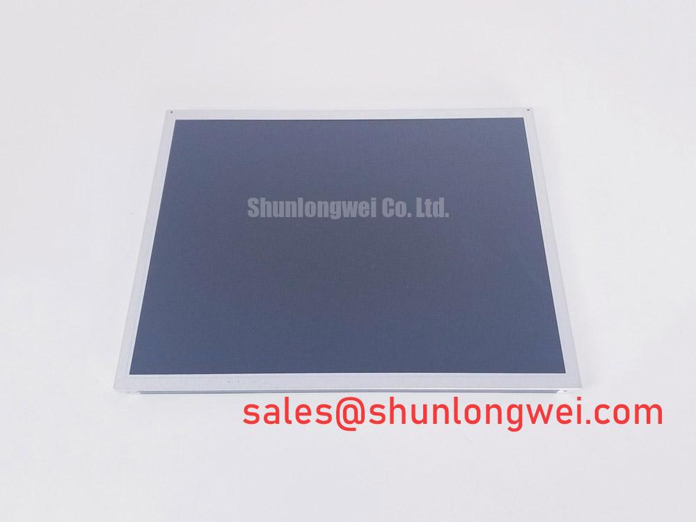
Place the AUO G150XTN03.3 on an ESD-safe bench and run a primary-color inspection before connecting it to the machine control system. Display red, green, and blue test fields separately, then use a uniform white field and a full black field to distinguish pixel-line irregularities from illumination problems. Look for narrow vertical or horizontal interruptions that remain fixed while the test image changes. These patterns can point toward a connection or driver-area issue, while broad luminance variation requires a separate backlight and optical inspection.
A 45-degree flashlight inspection is useful when the screen appears dark but the active image is still present. In a controlled room, angle the light across the front surface rather than directly into it. A faint image, edge glow, or shadow transition can help separate an illumination fault from a display-data fault. This test is qualitative: compare the result with a known-good panel or the original machine display instead of assigning a universal resistance or voltage threshold.
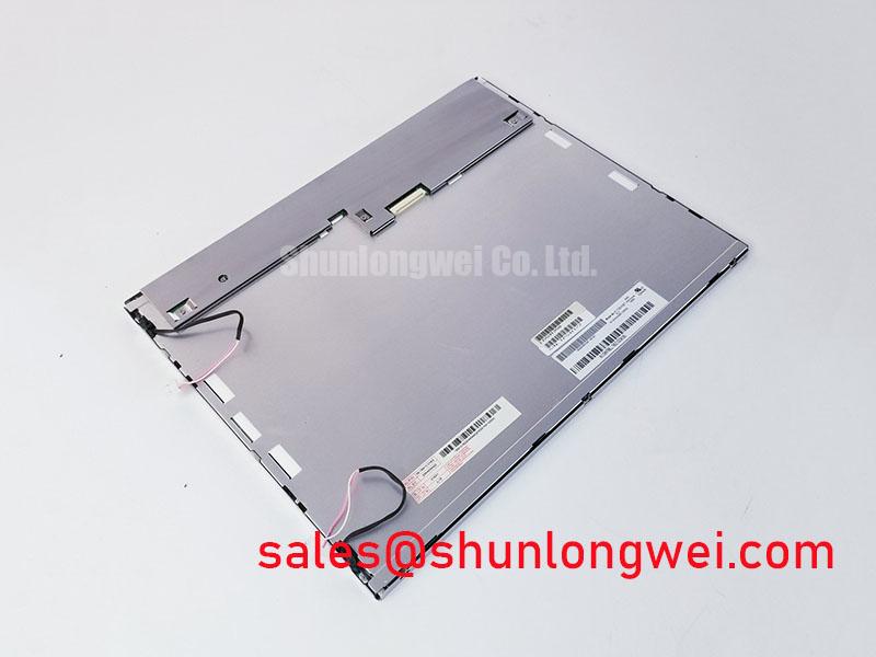
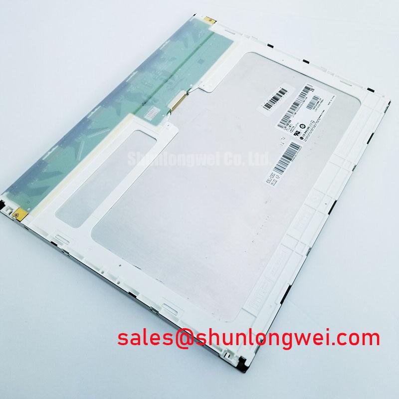
Bonded driver and flexible interconnect areas deserve particular care during handling. Do not press the bonded edge, twist the glass while lifting it, or apply force through the flexible connection region. A line defect that changes when the frame is touched should be treated as a mechanical or interconnect investigation, not immediately as a controller-board failure. Capture the color-field results before removing the original display so the replacement evaluation has a clear reference.
Cold commissioning requires a different interpretation of response time. At sub-zero temperatures, liquid-crystal viscosity can increase and make grey-to-grey transitions appear elongated even when the video source is stable. If the equipment operates around −20°C to −30°C, designers should evaluate the panel’s actual environmental specification, enclosure temperature profile, and any approved heater-control arrangement from the original equipment documentation. A heater strip is not identified as an integral feature of this panel and should not be treated as a standard accessory.
Suppressing Acoustic Capacitor Buzz and EMI Emissions across 200 Hz to 1 kHz PWM Frequencies
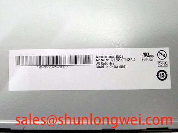
Check the backlight architecture in the original terminal before selecting a driver or troubleshooting dimming. The product information supplied for G150XTN03.3 identifies the display as a TFT-LCD active-matrix module, but it does not establish a universal backlight voltage, current, connector pinout, or lamp technology. The system integrator should verify these values from the original panel documentation and the machine wiring before applying power.
If the existing assembly uses a CCFL inverter, cold ignition can generate a high-voltage acoustic and electromagnetic environment that is separate from the LCD signal path. The inverter’s specified ignition range, transformer mounting, cable routing, and shielding should be evaluated as a complete assembly. A reported buzz may also originate from magnetics, mounting resonance, or PWM interaction, so compare the sound with the backlight disabled and then inspect the driver waveform using appropriately rated probes.
For a constant-current LED driver, assess brightness control across the intended PWM range, including the 200 Hz to 1 kHz region if supported by the driver. The practical test is to observe minimum brightness, intermediate levels, and full output while checking for visible modulation, camera banding, audible noise, and supply ripple. A nominal 1000:1 dimming claim belongs to the selected driver unless the panel documentation explicitly assigns it to the display assembly.
Long-term brightness figures also require source separation. A 50,000-hour point to 50 percent brightness is commonly used as an LED backlight-life reference, but it must not be presented as the service-life rating of this AUO module without an applicable manufacturer specification. For maintenance planning, record operating temperature, drive current, duty cycle, and enclosure airflow because these conditions influence the light source and driver independently.
EMI evaluation should include the complete HMI assembly: display cable, backlight wiring, controller board, enclosure, and protective earth arrangement. The LCD panel itself should not be described as independently certified to an equipment-level EMC standard. When interference appears only during dimming, correlate the event with the PWM edge timing and cable position before changing the panel.
Polarizer Durability and Optical Retardation Film Inspection under Direct Industrial Lighting
Inspect the front polarizer under the actual lighting direction used at the operator station. Direct industrial luminaires can expose surface haze, reflections, pressure marks, and viewing-angle color changes that are difficult to see under diffuse bench lighting. Compare the display at the normal operator position and at the expected upper, lower, left, and right observation angles. The viewing-angle behavior of LCDs is influenced by panel mode, optical stack, contrast condition, and measurement convention; the general principles are outlined in Viewing Angle Characteristics in LCDs.
Do not infer that a TN, IPS, or MVA optical mode is present unless the relevant panel documentation confirms it. Grayscale inversion, color shift, and contrast loss can vary by viewing direction, and a full symmetric viewing cone such as 85°/85°/85°/85° must be treated as a specified optical rating only when published for the exact display configuration. The same discipline applies to anti-glare treatment: surface etching, coating, and optical retardation details should be verified from the panel data rather than assumed from appearance.
For a factory automation machine tool or HMI operator terminal, inspect the screen with the machine’s real status colors, alarm pages, and numeric fields. A panel can appear acceptable on a static white pattern yet show poor readability when dark graphics are placed beneath overhead lighting. Use the same graphics, brightness setting, and viewing position for the original and replacement units. Industrial display technology references from Tianma NLT Industrial TFT-LCD Display Technologies can provide useful background on display and optical evaluation, but they do not replace AUO-specific specifications.
Clean the polarizer with a method approved for the original equipment. Avoid solvents, abrasive wipes, and concentrated pressure at the edges. Optical marks that disappear when the viewing angle changes may be reflections or retardation effects; marks that remain fixed across color fields and lighting directions should be documented with photographs for engineering comparison.
Chassis Fastener Tightening and Optical Mura Inspection
Mechanical fit should be checked before tightening any bezel or mounting frame. Confirm the opening, support ledges, connector clearance, cable bend path, and glass-to-frame contact conditions against the original terminal. Use the manufacturer’s mechanical drawing and the applicable assembly instructions to verify dimensions and mounting requirements rather than assuming a standard form factor establishes compatibility.
Where the chassis specifies M3 fasteners, a cross-pattern tightening method is a practical Design Consideration for distributing frame pressure, while the actual torque must come from the chassis drawing, fastener material, gasket arrangement, and panel assembly instructions. After fastening, repeat black, white, and mid-grey tests to identify localized dark zones or pressure-related mura.
Optical non-uniformity can be affected by bezel distortion, uneven support, cable compression, or contact between the display edge and enclosure. Release the frame, reposition the panel without forcing the glass, and compare the result before assigning the defect to the optical stack. Vibration and shock qualification belong to the complete HMI assembly; the mounting structure, isolators, connector retention, and cable strain relief should be evaluated together.
For LVDS integration, match the replacement interface to the original controller documentation. Verify connector orientation, lane assignment, clock polarity, pixel packing, and JEIDA or VESA data formatting before powering the panel. Where differential routing is used, maintain a continuous reference plane, minimize unnecessary stubs, and keep related pairs physically consistent. A 100 Ω ± 10 percent differential target and a skew budget of 50 ps or less may be used as board-level design references when they are required by the selected interface specification, not as confirmed electrical ratings of the LCD module.
💡 Pro Tip: Keep the differential clock and data paths closely matched through the controller-to-panel transition, then verify image stability with the machine’s real cable and enclosure installed rather than relying only on an open-bench test.
For broader enclosure, environmental, and service-planning considerations, engineers can consult Industrial Display & HMI Solutions. The G150XTN03.3 should be released to production only after its physical interface, power requirements, backlight control method, optical behavior, and mounting arrangement have been matched to the original HMI design.