Content last revised on September 28, 2026
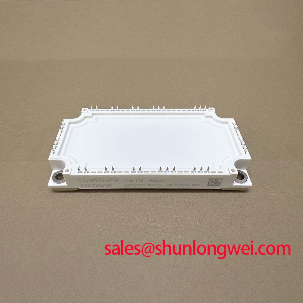
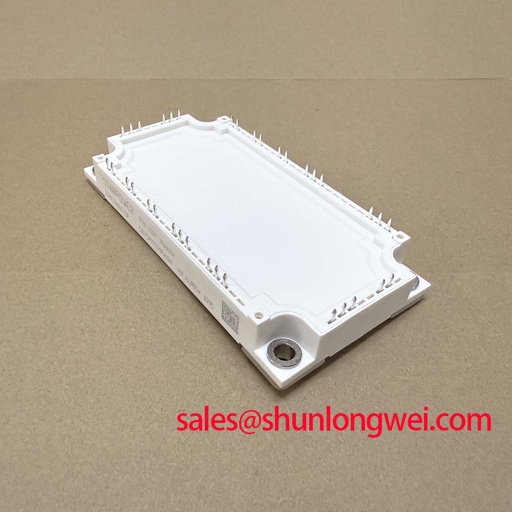
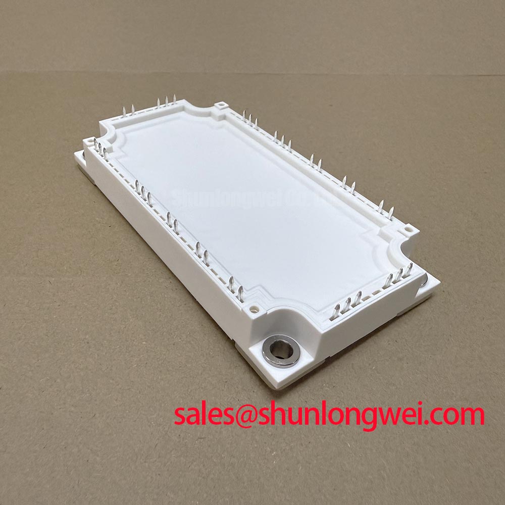
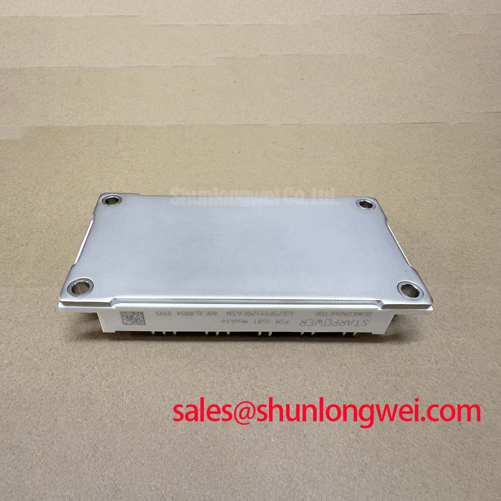
Preventing Spurious Faults: Managing High C Rate Battery Cycling Swing Guidelines for GD75P1Y120C6SN
In a commercial string inverter or microgrid energy storage cabinet, the power path can reverse between battery racks and the DC link during charging, discharging, and peak shaving. That operating pattern should be treated as a system level thermal investigation rather than as a simple current rating check. Designers should review the measured DC link waveform, phase current balance, switching temperature, and cooling airflow during both directions of active power flow.
The 75 A rating is specified at Tc = 80°C; it is not a universal guarantee for every enclosure temperature, switching frequency, overload profile, or cooling condition. During commissioning, compare the three phase current waveforms and inspect the NTC feedback under the highest expected battery cycling demand. If a fault appears only after repeated charge and discharge transitions, check busbar joints, cooling path restriction, gate supply stability, and thermal interface condition before attributing the event to the module itself.
Busbar geometry should minimize the commutation loop area and reduce stray inductance that can increase turn off voltage overshoot. The final clearance, creepage, capacitor placement, and laminated busbar arrangement remain system determined. Engineers evaluating the switching network can also consult IGBT Design & Integration for practical gate drive and thermal management references.
GD75P1Y120C6SN Circuit Protection & Reliability: Calibrating Multi Module Parallel Current Sharing
When parallel power paths are considered, static current sharing should be evaluated from the actual electrical characteristics of every installed device, busbar symmetry, cooling condition, and gate drive timing. The typical 1.85 V VCE(sat) at 75 A provides a useful comparison point, but it should not be treated as a complete parallel sharing guarantee. Measure collector current and case temperature on each path under representative load transitions.
Dynamic balance depends heavily on equal gate loop geometry. Keep the gate and return conductors arranged with matching impedance, avoid routing high di/dt power conductors alongside sensitive gate wiring, and verify the complementary interlock in the actual controller. Dead time must be selected from the switching characteristics, driver delay, temperature range, and measured commutation behavior. Excessive dead time can increase conduction loss, while insufficient dead time can create cross conduction.
For replacement evaluation, the related BSM22GD120D may be reviewed as a separate device option, but electrical, mechanical, thermal, and control compatibility must be confirmed by the system engineer rather than assumed from package similarity.
Transient Dynamics & Electrical Design: Galvanic Gate Drive Isolation, Reinforced on GD75P1Y120C6SN
The gate driver interface should be checked as an isolation system, not only as a logic signal source. If the application requires reinforced galvanic isolation above 5 kV or common mode transient immunity above 100 kV/µs, those values must be confirmed from the selected driver and isolation barrier documentation; they are not official specifications supplied here for the GD75P1Y120C6SN.
During bench testing, observe the gate to emitter waveform at the module terminals with suitable differential probing. Look for unintended pulses during rapid collector voltage movement, uneven turn on timing, ringing, and excessive negative or positive excursion. Gate loop inductance and driver output impedance should be controlled through compact routing and appropriate damping selected by measurement. The system designer should verify peak voltage margins against the DC link during switching tests instead of relying on nominal driver values.
For inverter output filtering and conducted noise review, the reference material on common mode chokes and EMI filtering and LC filter behavior can support broader topology analysis. The IGBT module itself should not be described as independently holding an overall EMC certification for the completed equipment.
Preventing Spurious Faults: Thermal Paste Degradation Prevention and Mounting Guidelines for GD75P1Y120C6SN
Thermal inspection should begin with the heatsink surface, mounting flatness, interface material condition, and airflow direction. Aged or uneven thermal compound can create localized temperature rise even when the electrical waveform appears normal. The correct interface material, application thickness, void control, and any compensation for baseplate curvature must be established from the heatsink and assembly design; the supplied product data does not define a universal thermal paste thickness or screw torque.
Mounting fasteners should be tightened progressively in a crosswise sequence using the equipment manufacturer’s specified hardware and torque procedure. After commissioning, compare case temperature across the module and inspect the heatsink for blocked fins, dust accumulation, and fan degradation. ⚠️ Maintenance Note: Isolate power before inspection, and periodically monitor contact temperature while checking the cooling airflow and terminal tightness.
Where a field fault follows a heatsink service, verify the DC bus discharge state, terminal polarity, gate wiring, NTC connection, and thermal contact independently. A controlled low energy test followed by oscilloscope review is preferable to replacing multiple power components without evidence.