Content last revised on October 13, 2026
Preventing Localized Light Guide Plate (LGP) Compression Warp on Dark Screen Fields
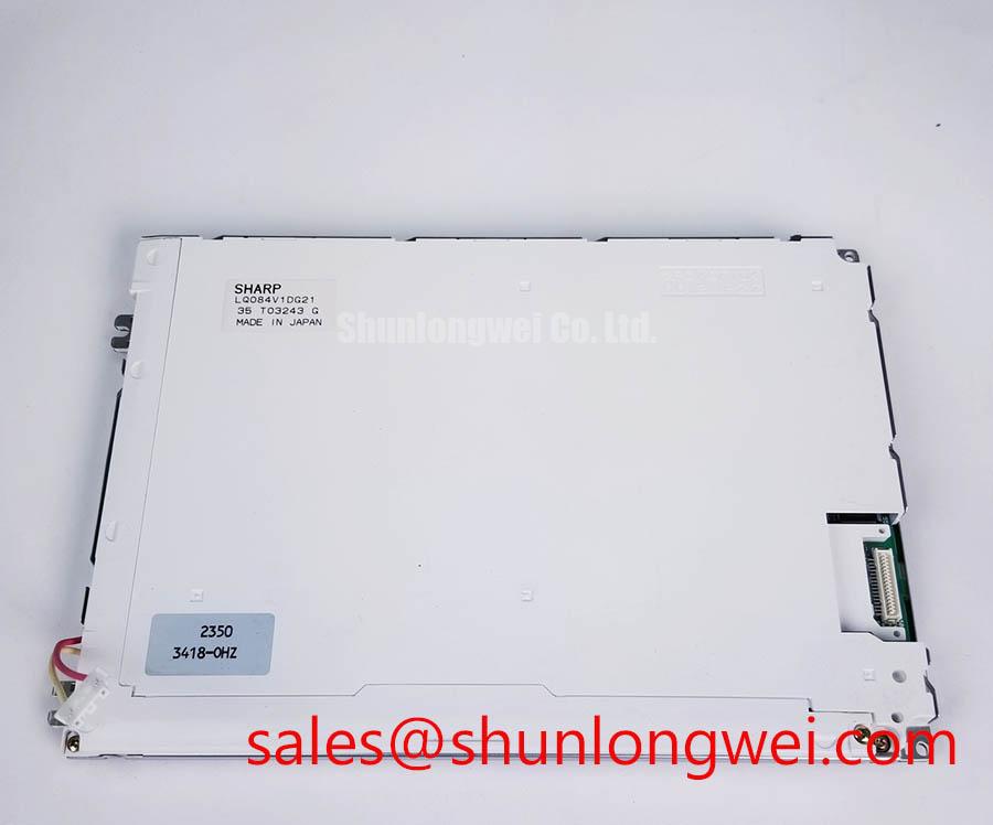
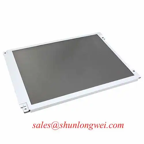
- Inspect the unpowered LA084X01-SL01 for frame distortion, connector damage, and pressure marks before fitting it into the equipment bezel.
- Check cable orientation, contact alignment, and latch engagement against the original display assembly.
- Prepare full-screen black, white, red, green, and blue patterns for pixel, line-defect, and illumination checks.
- Record the mounting arrangement and existing controller settings before changing the panel or its cable.
The LG Display LA084X01-SL01 is a TFT-LCD active matrix color display module in the industrial LCD/HMI panel category. Incoming inspection should distinguish defects visible on an unsupported bench assembly from changes introduced by the enclosure. That distinction helps repair teams separate panel evaluation from mounting, cable, and controller problems.
| Product identification | Specification or verification requirement |
|---|---|
| Model | LA084X01-SL01 |
| Manufacturer | LG Display |
| Product category | Industrial Grade LCD/HMI Panel |
| Module construction | TFT-LCD Active Matrix Color Display Module |
| Specification status | Verify against current manufacturer documentation. |
| Electrical, optical, and mechanical acceptance values | Consult Datasheet: dimensions, resolution, supply requirements, connector assignment, interface timing, backlight requirements, and environmental limits. |
Compare a black test field before and after bezel installation, keeping the image settings, viewing position, and ambient light unchanged. A localized bright patch that develops during mounting warrants inspection of enclosure contact points and frame loading; it does not independently establish damage to an internal light guide.
Design Consideration: check the bezel opening, support surfaces, cable exit clearance, and fastener seating against the mechanical drawing. The enclosure should support the assembly without forcing its frame into alignment. Where multiple fasteners are present, progressive cross-pattern tightening can help distribute loading, but screw size and tightening torque must follow the applicable assembly specification rather than a generic workshop value.
Repeat the dark-field inspection while comparing the panel outside the bezel with its installed condition. Photograph any changed pattern at the same exposure. Reflections, viewing-angle effects, and camera processing can otherwise exaggerate apparent differences. Avoid pressing the display surface to demonstrate a suspected pressure defect.
Design Consideration: evaluate brightness control separately from mechanical mura. Sweep the controller’s supported dimming range and observe low-brightness stability, audible noise, and spatial uniformity. If pulse-width modulation is part of the documented backlight architecture, assess its waveform and duty-cycle response at the driver. Select operating conditions through system testing rather than assigning a universal dimming frequency to this panel.
💡 Bench Tip: With power isolated and ESD protection in place, seat the display cable squarely before closing its latch rather than using the latch to pull a misaligned cable into position.
Single Vertical Hairline Defect & Sub-Pixel Column Driver Open-Circuit Localization
Display red, green, and blue fields in sequence and record whether the vertical hairline remains at the same pixel position on each pattern. Follow with white, black, and grayscale images to distinguish a fixed column anomaly from content-dependent artifacts. These observations narrow the investigation without proving a particular internal connection failure.
Design Consideration: compare the result with a known-good signal path using compatible equipment. Inspect accessible cable contacts and connector retention before attributing a persistent line to the panel. A line that changes with cable seating, image timing, or controller substitution needs further interface investigation; a stationary defect across controlled comparisons supports a different diagnostic direction.
For a dim or apparently blank screen, oblique flashlight illumination can help reveal whether an image is still present. A visible image under external illumination directs attention toward the illumination chain, but neither the flashlight angle nor the observation identifies a specific driver fracture. Do not flex the frame or press along the panel edge as a localization technique.
Engineering Recommendation: use the documented interface type and timing table to assess transmitter compatibility. Clock jitter, data setup and hold, cable loading, and receiver timing must be evaluated together at the receiver connection. Environmental testing should remain within the documented operating range. TTL timing checks and LVDS differential measurements are different procedures and should not be treated as interchangeable.
For replacement assessment, place NL8048BC19-02KD alongside LA084X01-SL01 in a compatibility worksheet. Compare mechanical fit, resolution, connector assignment, image orientation, and controller requirements before considering either unit for a CNC operator panel or robot teach pendant; a comparison link does not establish interchangeability.
Polarizer Durability & Optical Retardation Film Inspection under Direct Industrial Lighting
Inspect white and mid-gray fields under both controlled bench lighting and the intended installation lighting, noting reflections, surface marks, color shift, and loss of text contrast. Keep the viewing position repeatable so that an angular contrast change is not mistaken for a new surface defect.
Design Consideration: distinguish surface glare from viewing-angle behavior. Move the light source while holding the viewing position fixed, then change the viewing position while holding the light source fixed. This separates reflected illumination from changes in displayed grayscale. Do not infer TN, IPS, MVA, a symmetric viewing cone, or a particular retardation-film construction from the model number.
Surface inspection should use an approved cleaning method and nonabrasive handling. An external touch overlay or protective window can introduce additional reflections and alter apparent brightness. Glove operation and wet-surface touch response belong to the selected touch sensor and controller, not to the LCD module alone. Evaluate these accessories as part of the completed optical stack.
The Tianma NLT Industrial TFT-LCD Display Technologies resource provides industry context for display technology and optical selection; it is not an LG Display specification for LA084X01-SL01. Use technology comparisons to frame inspection questions, not to transfer another panel’s optical ratings.
Design Consideration: record center and edge luminance together with color consistency after a repeatable stabilization period. Brightness retention is not the same measurement as MTBF. Assess any aging claim against its stated drive conditions, temperature, measurement method, and endpoint rather than applying a generic backlight lifetime to this module.
L70/B50 LED Lifetime Reliability Verification
Trend luminance alongside accessible frame and driver temperatures while the display operates in its intended enclosure. A repeatable thermal map helps identify localized heating and distinguish temperature-related brightness changes from controller dimming or measurement drift.
Design Consideration: any added heat spreader must preserve mounting clearance and avoid concentrating pressure on the frame. Its dimensions, material, and contact arrangement are system-level decisions supported by thermal and optical measurements. Neither internal optical materials nor their aging behavior should be inferred from an external temperature reading.
L70 describes retention of seventy percent of initial luminous output; B50 describes the point at which fifty percent of the tested population reaches a specified lifetime criterion. They do not establish an LA084X01-SL01 service-life rating, and L70 is not a half-brightness endpoint. A meaningful claim requires an applicable test report with defined operating conditions and statistical treatment.
Engineering Recommendation: assess backlight protection through the documented driver circuit and its fault outputs. Open-circuit, short-circuit, and overvoltage behavior should be checked using the driver manufacturer’s approved procedure. The LQ6AW31K offers a separate display-solution comparison, not an established backlight-driver accessory for this module.
For a documented differential interface, preserve pair balance and evaluate impedance discontinuities, skew, and common-mode disturbance against transmitter and receiver requirements. Correlate display artifacts with nearby switching activity without assuming that every artifact is electromagnetic interference. The Industrial Display & HMI Solutions engineering guide provides broader integration context; acceptance remains a system-level test of image stability, cabling, grounding, thermal behavior, and protection response.