

Content last revised on November 22, 2026
Suppressing Ghosting and Crosstalk via Precision Multi-Level Bias Voltage Dividers
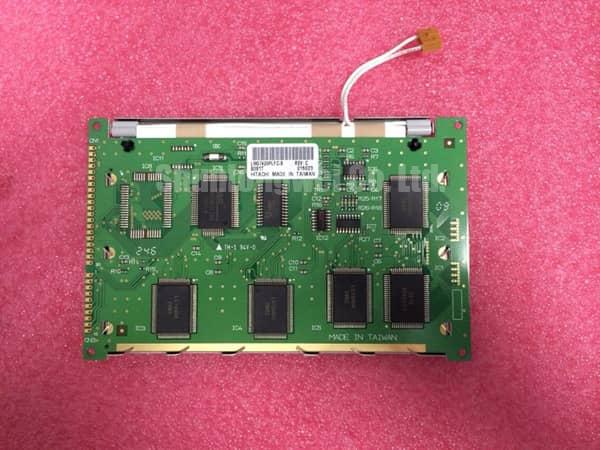
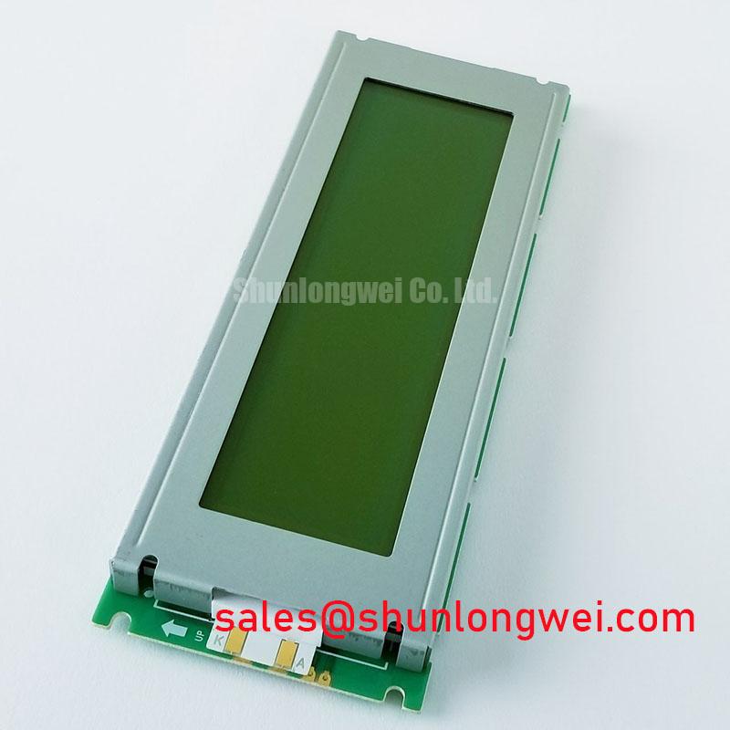
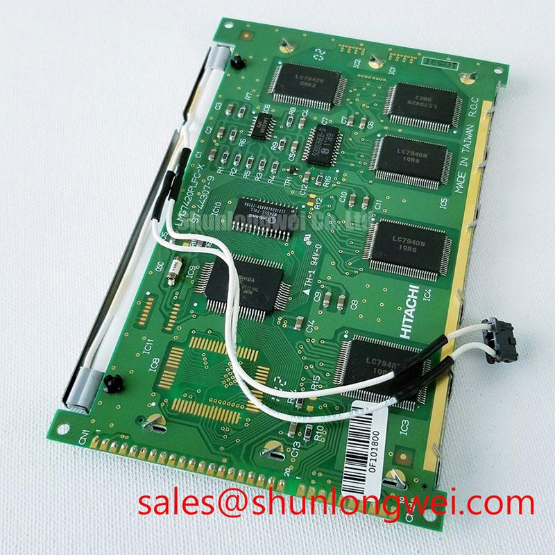
Observe the contrast supply at the LMG7420PLFC-X display connector while alternating between sparse text and densely populated patterns. As a Design Consideration, pattern-dependent contrast changes can help identify interaction between the bias network, supply impedance, and display loading. Measure relative to the designated display return rather than an arbitrary chassis point, and distinguish genuine ripple from probe-loop pickup.
Passive-matrix addressing depends on controlled differences between selected and unselected pixel drive waveforms. A disturbed bias ladder can reduce that separation, making inactive areas appear shaded or adjacent characters less distinct. Compare the divider nodes and their supporting supply under the same image conditions before replacing components. Divider ratios, component tolerances, and loading should follow the established controller design rather than a generic contrast adjustment recipe.
For temperature-dependent fading, an Engineering Recommendation is to compare contrast behavior with the bias output and any existing temperature-compensation network as the assembly reaches thermal equilibrium. Where the controller incorporates a thermistor, check its electrical continuity and thermal placement. A sensor influenced primarily by a nearby heat source may not represent the display temperature. The required compensation characteristic remains a controller-and-panel integration decision.
Supply coordination also includes the illumination subsystem, where fitted to the equipment. Separate contrast-rail disturbance from illumination changes by observing each circuit independently. The LM10V331 is another display product for separate documentation review, not an established backlight driver or electrically interchangeable companion for this panel.
Data Setup & Hold Time Margin Verification on High-Capacitance Flat Ribbon Flex Cables
Compare signal transitions at the controller output and display connector before attributing unstable characters to the LCD itself. As a Design Consideration, ribbon-cable capacitance, return-path discontinuities, and connector degradation can change edge shape and reduce timing margin at the receiving end. Preserve the original cable routing during the first measurement so the test represents the installed assembly.
Where the equipment schematic identifies FLM, LP, and CP signals, evaluate frame synchronization, line transfer, and data sampling against the controller and panel timing requirements. These names describe a common passive-matrix control arrangement; they are not a verified pin assignment for this exact part. Check data stability around the relevant sampling edge, including startup and changing image content, rather than judging timing from clock frequency alone.
The Low-Voltage Differential Signaling (LVDS) Interface Architecture explains differential signaling, but it does not establish that this panel uses LVDS. Avoid transferring differential termination practices onto an unidentified interface. When interference follows nearby drive operation, compare signal integrity and return-path behavior with the interfering equipment inactive and active; that investigation does not establish system EMC compliance.
Replacement evaluation should retain the complete suffix. The related LMG7420PLFC provides a useful comparison point, but a shared model stem does not prove connector, timing, or mechanical compatibility.
| Comparison item | LMG7420PLFC-X | LMG7420PLFC |
|---|---|---|
| Manufacturer | KOE / Hitachi | Consult Datasheet |
| Display form factor | FSTN / STN monochrome passive matrix | Consult Datasheet |
| Electrical and mechanical interchangeability | Match connector assignment, supply requirements, timing, outline, and mounting drawing before substitution. | |
For power sequencing, an Engineering Recommendation is to compare logic supply, contrast supply, and control-signal activity against the approved equipment startup and shutdown sequence. Persistent abnormal drive or unintended DC content warrants investigation, but should not automatically be described as latch-up. The same compatibility review applies when evaluating a railway passenger information terminal or cab signalling display; suitability and system approval require separate assessment.
Cold-Start Response Time Viscosity Damping across Sub-Zero Machine Environments
Record whether slow transitions affect the entire image or remain confined to fixed regions during a cold start. As a Design Consideration, liquid-crystal response generally slows as temperature falls, while persistent local shading can involve mounting stress, optical deterioration, or drive nonuniformity. Compare identical patterns after thermal stabilization without exceeding the equipment’s approved operating conditions.
Refresh frequency and optical response are different quantities. The display refresh rate reference explains the former; increasing refresh activity does not necessarily correct slow optical transitions. Excessive changes to controller timing can instead disturb addressing or contrast. Preserve the established drive configuration while separating temperature effects from signal faults.
Inspect the front optical surface under consistent illumination and viewing angle. Haze, edge lifting, and localized bubbling should be documented independently of electrical measurements. Do not assume a particular polarizer chemistry, transflective construction, or antiglare treatment from the panel family name. Changing brightness alone cannot establish the source of optical degradation.
During transfer from a cold environment to a warmer, humid workspace, an Engineering Recommendation is to let the assembly stabilize under the site’s condensation-control procedure before energizing it. The Built to Last Technical Reference offers broader enclosure and environmental context, rather than model-specific qualification evidence.
Bezel Mechanical Frame Clamp Uniformity & Uniform Gasket Pressure Distribution
Check bezel seating and gasket compression around the perimeter before increasing fastener load to address missing lines or uneven contrast. As a Design Consideration, distorted mounting surfaces can transmit uneven stress into a display assembly. Use the equipment mounting specification and inspect for trapped cables, displaced seals, or debris that prevents the frame from seating evenly.
Missing rows or columns can involve connector seating, conductor continuity, controller output, or panel faults. Compare the affected region with the signal path before disturbing the assembly. An elastomeric contact strip should only enter the repair procedure when the service documentation identifies that construction; neither a compression pressure nor a cleaning solvent should be assumed suitable for this model.
Where authorized servicing exposes contacts, follow the approved cleaning method and avoid transferring solvent onto optical films or bonded edges. Reassemble without twisting the frame, then compare uniform test patterns before and after fastening. Any pressure-related image change is diagnostic evidence, not permission to exceed the specified mounting load.
Maintenance Note: Periodically inspect enclosure airflow paths and gasket seating, and isolate power before reseating the display cable.