
Content last revised on September 11, 2026
Sharp LQ150X1DG51 Industrial LCD Module
Before installing the Sharp LQ150X1DG51, inspect the display module for bezel damage, connector contamination, uneven frame pressure, and signs of moisture exposure, then confirm the replacement identification against the original equipment documentation.
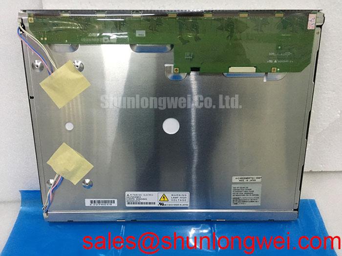
The LQ150X1DG51 is an industrial grade LCD/HMI panel supplied as a Sharp TFT LCD display module. The available factory specification identifies the product category, manufacturer, enclosure format, and official specification status. Electrical interface details, optical values, dimensions, backlight configuration, timing requirements, and mounting geometry should be verified from the original panel documentation before system integration.
| Parameter | Official specification status |
|---|---|
| Model | LQ150X1DG51 |
| Manufacturer | Sharp |
| Product category | Industrial Grade LCD/HMI Panel |
| Package or enclosure | TFT LCD Display Module |
| Specification status | Official Factory Spec Verified |
For a high voltage substation protection or SCADA dispatch console, the practical compatibility check should cover the mechanical opening, display cable routing, host controller interface, power sequencing, touch or keypad arrangement, and enclosure airflow. The panel category alone does not confirm compatibility with a particular controller. The system integrator should verify the required supply voltage, signal format, pin assignment, timing, and backlight control method from the original panel documentation.
High Humidity Storage Margins and Delamination Prevention Protocols
During incoming inspection, keep the module sealed until it has reached the workshop environment gradually. Moving a cold display directly into a warm, humid cabinet can create condensation around connectors, the bezel perimeter, and internal interfaces. This is a general industrial handling consideration rather than a published environmental rating for the LQ150X1DG51. The available product information does not establish a guaranteed storage condition of 60°C and 90% relative humidity, so those conditions must not be treated as an official rating for this model.
Inspect the front surface and perimeter for lifting layers, cloudy zones, edge separation, stains, or pressure marks. If the replacement panel has been stored in a cold warehouse, allow the complete assembly to stabilize before energizing it. Moisture control should be managed at the enclosure level through cabinet sealing, controlled ventilation, and suitable desiccant or environmental control where required by the equipment design.
Low temperature operation can alter liquid crystal response characteristics, producing visible response lag or temporary gray level nonuniformity. This is a general LCD design consideration and does not establish a specific gray to gray performance value for this Sharp module. Engineers evaluating a sub-zero installation should observe moving text, alarm transitions, and trend graphics during environmental testing rather than relying only on a static test image.
Do not assume that the LQ150X1DG51 includes optical bonding, a particular perimeter sealant, or a specified anti-glare coating unless the original Sharp documentation confirms it. If direct sunlight is present at a control desk, evaluate readability through the complete cabinet window, cover glass, viewing angle, and ambient illumination arrangement. A contrast ratio above 500:1 at 50,000 lux has not been provided as an official specification for this product and therefore requires system-level verification if it is a project requirement.
The same inspection logic applies when comparing a same-size or resolution reference. The LMS700KF01-001 may be reviewed as a separate display reference, but its presence does not establish interchangeability with the LQ150X1DG51. Mechanical dimensions, connector orientation, signal timing, and optical performance must be compared from their respective documentation.
Edge-Lit LED Rail Thermal Dissipation and Light Guide Preservation
Backlight construction should be confirmed before any thermal modification is planned. The supplied factory information identifies the LQ150X1DG51 as a TFT LCD display module but does not confirm an edge-lit LED architecture, a PMMA light guide plate, a particular rail arrangement, LED lifetime data, or an L70/B50 rating. A maintenance team should therefore avoid adding heat spreaders, heater strips, or replacement driver boards solely from visual similarity to another panel.
During bench evaluation, check the display after a representative operating period with the module installed in its intended bezel. Compare luminance uniformity near the edges and center, inspect for localized bright or dark areas, and record the enclosure temperature at the display mounting region. These observations help separate panel behavior from cabinet airflow problems, backlight driver behavior, or mechanical compression.
Heat management is a design consideration. Keep airflow paths clear, prevent the bezel from blocking intended ventilation, and avoid pressing thermal pads or rails against areas not identified for contact by the panel documentation. A chassis modification should be validated for mechanical clearance, electromagnetic noise, service access, and optical uniformity before deployment.
Cold temperature testing should include startup, static screens, alarm transitions, and rapidly changing SCADA graphics. Liquid crystal response can become slower as temperature falls, while a backlight control circuit may have its own startup behavior. The LQ150X1DG51 documentation supplied for this page does not specify a guaranteed operating range, gray-to-gray response time, heater requirement, PWM frequency, or duty-cycle linearity. Those values should be taken from the original technical file or measured on the complete assembly.
When the display is used near power conversion equipment, route the display supply and signal cable away from high-current switching paths where the cabinet layout permits. This is a design consideration for reducing conducted and radiated interference; it is not a claim that the module independently complies with an equipment EMC standard. A system-level test should examine screen uniformity, intermittent lines, image resets, and communication errors under representative switching conditions.
A compatible display solution may include separate backlight or control circuitry, but the relationship between this panel and any companion device must be confirmed by documentation. The LQ150X1LG11 can be reviewed as a related Sharp display solution, not as an automatic replacement or confirmed driver match for the LQ150X1DG51.
Industrial Bezel Mechanical Envelope and Mounting Stress Control
Measure the cabinet aperture and mounting face before transferring the replacement panel. Check the available depth behind the bezel, cable bend space, fastener locations, connector access, and the position of any protective window. The official information available here does not provide the LQ150X1DG51 outer dimensions, active area dimensions, mounting hole pattern, or bezel tolerance. These values must be verified from the original drawing rather than estimated from the model designation.
Uneven frame pressure can affect the visible image through local stress, bezel marks, light leakage, or nonuniformity. This is a general mechanical integration consideration. Use a flat mounting surface, inspect the gasket for compression damage, and tighten fasteners progressively so that the frame is supported evenly. The supplied specifications do not define an approved screw size or tightening torque for this model, so a value such as 0.35 to 0.45 N·m must not be presented as an LQ150X1DG51 factory requirement.
Maintenance Note: Check the cabinet airflow path and the condition of the display gasket during scheduled service because dust accumulation or a flattened seal can increase thermal and mechanical stress.
For a substation console, the bezel should also shield the display from accidental contact without transferring cabinet vibration directly into the glass or frame. Designers should verify the enclosure resonance, support points, and cable strain relief during vibration testing. If horizontal bands, intermittent pixels, or localized dark areas appear after installation, inspect mounting stress and cable seating before assigning the fault to the LCD cell.
Do not apply adhesive, foam, thermal compound, or a replacement light guide component to the panel unless the service documentation identifies the permitted material and contact area. Unverified additions can change pressure distribution, obstruct heat flow, or interfere with connector access. A clean, controlled mounting interface is preferable to an improvised mechanical preload.
For a replacement assessment, compare the complete assembly rather than only the screen size. The original controller, timing behavior, connector keying, backlight drive, and mounting envelope determine whether a panel can be integrated. The LQ150X1DG51 should be treated as a Sharp TFT LCD display module with the stated category and manufacturer information, while every unlisted interface parameter remains subject to documentation review.
Eye Diagram Margin and Differential Noise Verification in High-Vibration Bays
Begin signal troubleshooting with power removed and the cable disconnected from the panel, following the equipment service procedure. Inspect connector alignment, contact cleanliness, cable shielding, and strain relief. Reconnect the assembly only after confirming the cable orientation. A display fault observed near a 400 V variable frequency drive can involve grounding, cable routing, controller timing, supply disturbance, or mechanical vibration; a single symptom does not establish one cause.
LVDS or other differential signaling should not be assumed from the product category alone. The LQ150X1DG51 factory context supplied for this page does not include a confirmed interface type, pin definition, common-mode range, eye mask, or cable length. The system integrator should verify the interface from the original Sharp panel documentation and match the controller accordingly. If an oscilloscope is used, compare the suspected channel with a known-good signal path while observing the complete system operating state.
A shielded cable can help control interference when its construction, termination, and cabinet grounding are appropriate, but a 360-degree shield connection or ferrite component should not be added as a universal prescription. The correct arrangement depends on the cable design, grounding topology, isolation requirements, and EMC test results. Any common-mode filtering must be evaluated for its effect on signal integrity and startup behavior.
Power sequencing deserves the same discipline. White screen behavior, residual images, or a missing image can be associated with supply order, reset control, backlight enable timing, controller initialization, or a loose connection. These observations require measurement against the original equipment sequence. The supplied information does not state the panel supply voltage, enable thresholds, reset timing, or discharge requirement, so designers should verify each value before changing the host controller.
PWM dimming frequency and duty-cycle linearity are also system dependent unless explicitly listed in the panel documentation. The requested range of 200 Hz to 1 kHz cannot be treated as an official LQ150X1DG51 specification. If the display is used for long periods with fixed SCADA graphics, evaluate brightness stability, image retention, operator readability, and the behavior of the complete backlight controller. Static image management belongs to the HMI software and system design as well as to the display module.
For broader engineering context on display selection, timing, optical behavior, and common integration assumptions, consult The Ultimate Guide to Industrial TFT LCD Technology. The LQ150X1DG51 product page should still be used together with the original panel documentation and the host equipment drawings when approving a repair or replacement.