

Content last revised on September 10, 2026
LTM150XH-L04 Identification and Service Scope
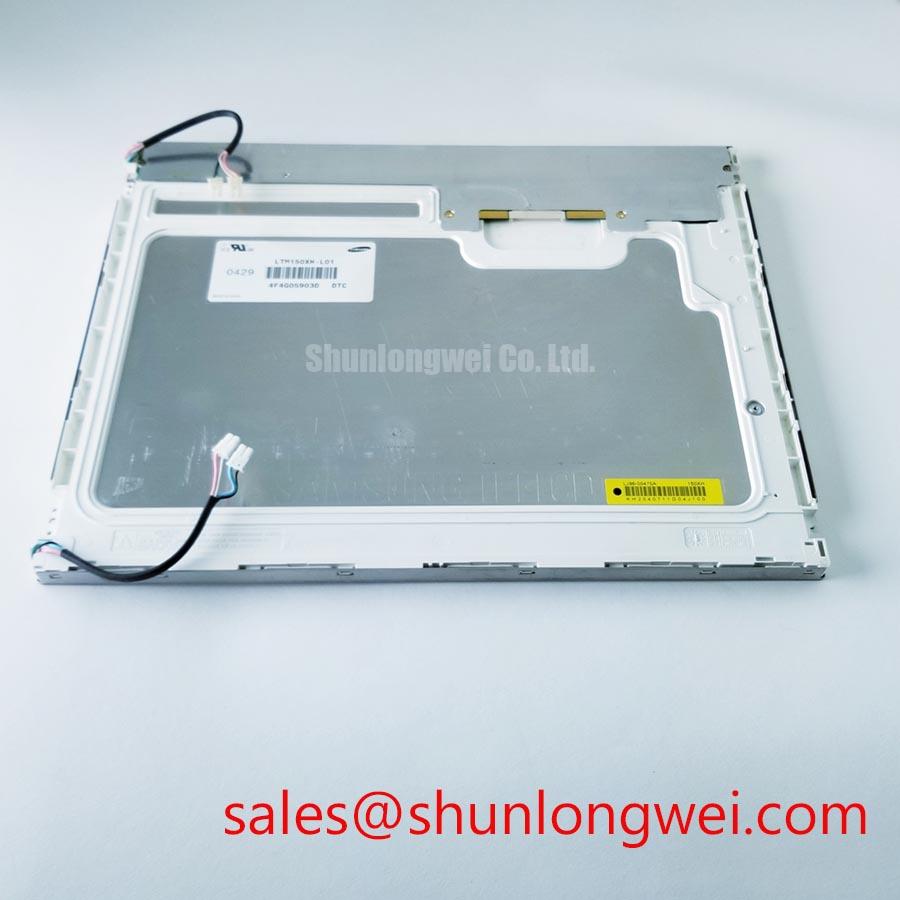
With the equipment de-energized, inspect the display face, perimeter frame, rear label, and connector area of LTM150XH-L04 before disconnecting the original harness. The identified product is a TFT LCD Display Module associated with Samsung. Confirm that the installed mechanical envelope, connector orientation, signal cable condition, and controller documentation match the original assembly before any replacement decision.
| Verified item | Specification status |
|---|---|
| Model | LTM150XH-L04 |
| Manufacturer association | Samsung |
| Product category | TFT LCD Display Module |
| Module construction | TFT LCD Display Module |
| Specification status | Model identity supplied; detailed specifications require confirmation from the applicable datasheet |
The available identification data does not establish the panel’s active area, resolution, luminance, backlight technology, interface pinout, logic supply, timing limits, optical ratings, or environmental limits. These items must be confirmed from the original panel documentation and the host equipment schematic. This distinction is important when the panel is being assessed for use in industrial HMI equipment or for compatibility review in diagnostic display assemblies.
Optical Luminance Degradation Curve & CCFL-to-LED Modernization Retrofit Pathways
Begin an optical assessment with the original panel and its original display controller connected as a known system pair. Display full white, full black, red, green, blue, and a low level gray image. Observe brightness uniformity, edge shading, flicker, image retention, and whether an image remains visible when the backlight appears absent. These observations help separate a possible illumination issue from a video timing or LCD cell issue, but they do not establish a single root cause without electrical measurement.
The available identification information for LTM150XH-L04 does not confirm whether its original illumination system uses CCFL or LED technology. A technician should therefore inspect the original panel documentation, inverter or driver board designation, and connector pin assignment before discussing a CCFL to LED conversion. CCFL systems can involve high ignition voltage, while LED systems require current controlled drivers; neither electrical architecture should be assumed from panel size, product family, or visual appearance.
An illumination retrofit is a system modification rather than a direct panel parameter. It can affect diffuser coupling, thermal behavior, mechanical stack height, dimming behavior, electromagnetic noise, and controller power sequencing. Where a host controller supplies an enable or dimming signal, the integrator should verify its signal type, polarity, timing relationship, and reference ground against the existing backlight circuit. Claims regarding acoustic noise, PWM dimming ratio, or operating life require documentation for the actual replacement driver and light source, not the display module identity alone.
Display data integrity must also be evaluated while brightness is changed. Clock jitter, data hold time, and differential signal quality are controlled by the panel interface requirements and host transmitter behavior. 💡 Pro Tip: Keep each differential pair routed as a controlled pair with closely matched physical path length, then verify image stability on the installed cable assembly rather than relying on bench appearance alone.
For broader diagnostic context on TFT operation, optical symptoms, and industrial display selection boundaries, consult The Ultimate Guide to Industrial TFT LCD Technology alongside the original LTM150XH-L04 documentation.
Incoming Benchtop Inspection: Panel Bond and Connector Integrity
Place the unpowered module on an ESD controlled, clean and nonconductive work surface. Inspect the front polarizer for pressure marks, the metal frame for distortion, the rear assembly for loose hardware, and the connector for bent contacts or damaged locking features. Do not flex the panel frame to test its rigidity. Mechanical stress can alter contact behavior or create symptoms that are not representative of the original equipment fault.
Use a three step primary color test after confirming that the host controller, supply arrangement, and interface mapping are appropriate for the specific module. First, show full red, green, and blue fields. Second, show full white and black fields. Third, show gray ramps and fine line patterns. Vertical or horizontal line defects, localized tint changes, intermittent areas, and missing image sections should be recorded across several power cycles. A repeated fault can guide the inspection toward the panel, cable, connector, controller output, or display configuration, but it should not be assigned to a particular internal bond structure without documented evidence.
A flashlight inspection at an oblique angle can be useful when an expected image is extremely dim. If image content is visible only under external illumination, inspect the backlight circuit, enable control, dimming control, driver output, cable seating, and the panel documentation. If the image remains absent, verify the host video source and the panel’s defined power sequence before attributing the symptom to the TFT module.
Terms such as COG, TAB, and ACF describe assembly technologies used in the display industry, but the available data for this model does not define its internal construction. Avoid probing bonded areas, pressing on edge electronics, or applying heat to the panel perimeter as a diagnostic shortcut. These actions can introduce new damage and obscure the original failure pattern.
Cold ambient conditions can slow visible gray transitions in liquid crystal displays. This is a display physics consideration, not an official temperature rating for LTM150XH-L04. When a machine exhibits slow image settling after cold startup, compare the panel behavior with a known good unit under controlled conditions and verify whether the equipment itself specifies a panel heater, enclosure warmup process, or temperature management method.
Mitigating Gray-to-Gray (GTG) Response Time Escalation during Cold-Start Machine Power-Up
Assess cold start behavior with motion patterns, gray ramps, and sharply changing image content rather than a static desktop image alone. Smearing, delayed shade transitions, temporary low contrast, and ghosting can arise from panel temperature, source timing, power sequencing, signal quality, or controller configuration. A practical investigation records ambient condition, warmup behavior, displayed pattern, source resolution, and whether the same symptom follows the panel or remains with the host equipment.
The supplied official information does not provide a gray to gray response time, operating temperature range, thermal cycle capability, contrast ratio, sunlight readability value, anti glare treatment, or perimeter sealant specification for LTM150XH-L04. It would be inaccurate to assign industrial temperature limits or direct sunlight performance to this specific module without its original datasheet. System integrators should verify these requirements from the original panel documentation and assess them against the intended enclosure, duty cycle, and ambient exposure.
For display terminals evaluated in high precision surgical navigation or ultrasound diagnostic environments, the panel should be treated as one part of a complete imaging chain. Image source format, scaler configuration, display calibration, enclosure cleaning procedure, protective cover construction, viewing angle, and ambient light all affect the observed result. Such equipment can have application specific validation obligations that exceed the electrical compatibility of a replacement panel.
Design Consideration: if a host system uses heating or controlled enclosure warmup, confirm that its sensing and control method belongs to the equipment design and is compatible with the panel documentation. Do not attach a heater strip, modify a perimeter adhesive area, or infer a permissible thermal range from a similar looking display module. Mechanical modification can affect flatness, optical behavior, and serviceability.
Technical literature can assist with general electronic reliability discussions, but it is not a substitute for the panel manufacturer’s specification. For example, IEEE Transactions on Industry Applications provides peer reviewed industrial electronics material, while display specific acceptance criteria must remain tied to the relevant panel and equipment documentation.
Interface Pin Count, LVDS Timing, Pixel Clock & Skew Compensation
Do not infer a 20 pin or 30 pin interface from the model identifier. The available verified data does not state the connector position, pin count, LVDS channel arrangement, logic voltage, pixel clock, display resolution, or JEIDA and VESA mapping. The system integrator should verify the required supply voltage from the original panel documentation. It is equally necessary to compare the original cable pinout with the replacement module before applying power.
LVDS and TTL are different signaling approaches and require different host interfaces. A connector that physically mates does not prove electrical compatibility. Before installation, trace the host controller output through the cable assembly and confirm the panel’s specified signal standard, lane allocation, clock relationship, data mapping, enable behavior, and grounding scheme. In differential LVDS systems, controlled impedance routing and paired conductors support signal integrity, while final acceptance should be based on measurements and image tests performed on the actual host system.
JEIDA and VESA mapping differences can alter color order or create abnormal image presentation when a transmitter and panel expect different bit assignments. Split images, wrong colors, unstable sync, intermittent sparkles, or a blank screen can indicate several possible causes, including mapping configuration, source timing, cable damage, power sequencing, grounding, or controller output integrity. Verify the waveform and image output against a known good signal path before changing panel settings or replacing supporting electronics.
Power sequencing must follow the original panel documentation. The host system should establish the required relationship among logic power, valid video data, panel enable control, and backlight control. Applying a guessed supply voltage or enabling the backlight before the defined logic state is established can create misleading fault symptoms and risks damage. During service, reconnect the display cable only when the equipment is fully de energized and observe connector keying without forcing the mating parts.
Where an existing industrial controller is being retained, document the original cable routing, shielding arrangement, grounding contacts, and connector latch position before removal. This preserves a repeatable baseline for post installation testing and helps distinguish panel compatibility issues from harness or controller faults.