

Content last revised on September 10, 2026
Dual Channel CCFL High Voltage Resonant Inverter Striking Voltage and Ignition Debugging
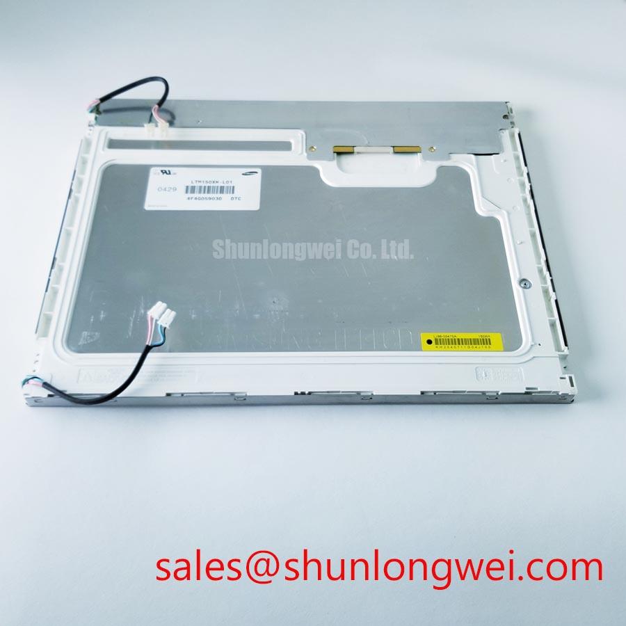
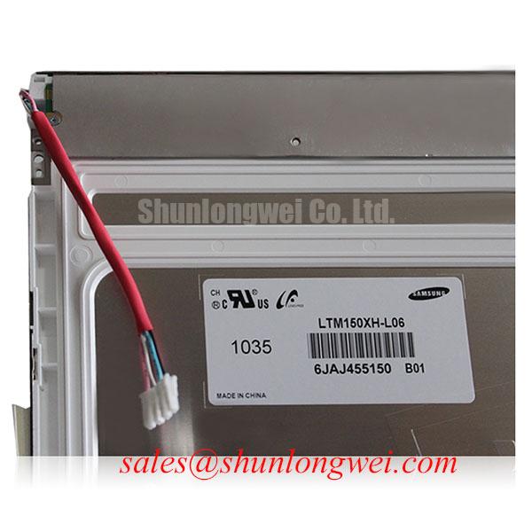
Measure the inverter output condition and inspect both lamp harness connections when the LTM150XH-L06 powers up with a dim image, intermittent illumination, flicker, or an audible high frequency noise. A stable image that disappears after startup can involve the backlight power path, while a permanently white, split, or unstable image can also involve panel signal timing. Isolate those paths rather than treating every dark screen as a backlight failure.
The official product identification confirms this unit as a Samsung TFT LCD Display Module, while its electrical input, backlight architecture, interface assignment, timing values, and optical limits must be matched to the original panel documentation. Do not infer the backlight type from panel size, connector appearance, or a similarly named panel. Older industrial display assemblies can use separate inverter boards, and the replacement panel must be evaluated as part of the complete display stack.
For a suspected high voltage lamp circuit, inspect the panel side connector seating, cable insulation condition, inverter board solder joints, and the enable or brightness control signal at the original controller. Compare startup behavior with a known good display assembly where available. A brief flash followed by shutdown may point to a protection response, an unstable harness connection, lamp aging, or an inverter issue; waveform comparison and connector inspection are more useful than assigning one cause from the symptom alone.
Signal integrity remains relevant during backlight diagnosis. Inspect the LVDS cable for crushed sections, incomplete latch engagement, contamination, and strain at the bend exit. Clock instability, poor data hold timing, or an intermittent ground reference can create image defects that appear only during vibration or temperature change. The system integrator should verify signal requirements and timing limits from the original panel documentation and host board schematic.
💡 Bench Tip: Disconnect power and use ESD protection before handling the panel cable, then insert the connector straight and fully parallel so the contacts lock without side loading.
When a replacement is being assessed for an industrial HMI or telematics display, retain the original inverter and cable assembly only after confirming compatibility at the assembly level. The panel itself should not be assigned system level electromagnetic compliance or lifetime claims without documented evidence from the equipment manufacturer.
Diffuser Film and Prism Sheet Thermal Buckling Prevention Under Continuous Full Duty Operation
Check the rear enclosure, bezel contact surfaces, cable routing, and heat producing boards when a display shows localized bright areas, edge discoloration, uneven luminance, or changes after prolonged operation. These visible conditions can originate outside the panel, including an obstructed enclosure vent, pressure from an uneven mounting frame, poorly located inverter hardware, or a warped protective window.
The LTM150XH-L06 should sit in a mechanically flat support arrangement that does not twist the panel frame or load the active display area. This is an Engineering Recommendation: distribute support through the intended mechanical features of the equipment enclosure, preserve cable movement clearance, and confirm that adjacent electronics do not impose local heat or pressure on the display assembly. Mounting geometry is determined by the original equipment design and the panel mechanical drawing.
Optical bonding, protective cover lenses, gaskets, and anti glare treatments belong to the host display assembly unless explicitly specified for the exact panel. They can improve resistance to dust ingress, reflected ambient light, and condensation in certain finished products, but they must not be assumed to be factory attributes of this Samsung module. When evaluating a bonded assembly, inspect the cover interface for contamination, edge lift, trapped moisture, and pressure patterns rather than making assumptions about the panel’s internal optical construction.
Long duration static pages deserve practical attention in industrial HMI equipment. Operators may leave alarms, machine status pages, maps, or service screens displayed for extended periods. Use the equipment’s intended screen management functions where available, and assess any persistent image retention after controlled content changes. Image retention can be affected by display technology, temperature, drive condition, brightness setting, and the content history. It should be recorded as an observed behavior, not used as proof of a single internal defect.
Where continuous full brightness is necessary, inspect the complete enclosure at operating temperature and compare brightness uniformity across the screen over time. Avoid placing insulation, adhesive, or rigid retainers against areas that the original equipment design leaves clear. For broader enclosure and display integration practices, review Industrial Display & HMI Solutions alongside the equipment’s own mechanical and thermal documentation.
Full Screen Primary Color AOI Screening: Stuck Sub Pixels and Background Uniformity Audit
Display full screen black, white, red, green, and blue test fields while viewing the LTM150XH-L06 at normal working distance and at close range to identify isolated bright points, dark points, lines, color casts, or uneven illumination. Keep the panel face clean and use a stable signal source so that dust, compression artifacts, and host graphics errors are not mistaken for panel defects.
A useful bench sequence begins with black for light leakage and unintended bright pixels, followed by white for broad luminance and color uniformity, then the primary color fields for stuck sub pixels and vertical or horizontal line behavior. Repeat the sequence after gently repositioning the LVDS cable and after a controlled power cycle. If a line changes when cable position changes, inspect the host connector, cable, and grounding continuity before attributing the fault to the panel.
A flashlight inspection at an oblique angle can help reveal surface scratches, cover lens defects, trapped particles, or mechanical pressure marks. It does not establish an internal cause by itself. A line defect, a backlight issue, and a host signal error can present differently under black and white screens, so record the pattern, test image, and cable position for comparison with the original display.
Ambient light can change perceived contrast dramatically. A viewing condition that is acceptable indoors can appear washed out near an open cab window or under direct sun. Anti glare coatings and sunlight readable assemblies must be treated as host equipment characteristics unless confirmed in the original documentation for this exact model. The VESA official portal is a useful reference point when reviewing standardized display interface terminology and display ecosystem practices.
Automated optical inspection can support repeatable incoming screening when multiple units are evaluated, but a careful human review remains valuable for edge pressure marks, surface contamination, and defects that appear only after warm up. Inspection methods used for solder void analysis, such as automated X ray inspection, apply to hidden soldered assemblies and do not replace optical panel testing.
20 Pin and 30 Pin Differential LVDS Timing, Pixel Clock and Skew Compensation
Verify the connector pinout from the original panel documentation and host display schematic before connecting any LVDS cable to the LTM150XH-L06. A connector with a similar pin count or physical profile is not confirmation of matching logic supply, signal mapping, enable control, or ground placement. Incorrect assignment can produce a white screen, color distortion, split image, unstable synchronization, or damage to connected circuitry.
Inspect the cable at both ends under magnification, paying close attention to recessed contacts, latch damage, shield termination, and conductors pulled loose near the strain relief. Use an oscilloscope only with an appropriate probing method for differential signals, then compare the clock and data activity against a known good host path where possible. This is a Design Consideration: preserve controlled differential routing and minimize unnecessary cable stress to reduce signal degradation, while the actual impedance, pixel clock, and timing requirements are determined by the panel documentation and controller design.
The system integrator should verify the required supply voltage from the original panel documentation. It should also verify the prescribed power sequencing relationship between logic power, data activity, display enable, and backlight control. Applying a generic timing value to an undocumented panel is not a safe substitution for the original host design. During troubleshooting, observe whether the panel receives stable logic power before valid video data and whether shutdown leaves unwanted residual image behavior.
JEIDA and VESA mappings are not interchangeable assumptions. A mismatch may create swapped colors, abnormal bit weighting, or irregular screen segmentation even when the connector fits and image timing appears present. Confirm the mapping in the panel documentation, cable drawing, and controller configuration before changing hardware. For equipment exposed to vibration, including displays evaluated for heavy earthmoving telematics installations, secure the cable path to the enclosure so motion is not transferred directly into the panel connector.
At low ambient temperature, liquid crystal response can visibly slow and transitions may look less uniform. Assess the complete display assembly at its intended operating condition, including the enclosure, heater provisions if fitted by the equipment manufacturer, controller timing, and protective lens. The panel should be integrated only after the original electrical, mechanical, and optical requirements have been verified against the host system.