Content last revised on September 15, 2026
M50100THC1600-8701 Thermal-Electrical Optimization: Evaluating Post-Surge Reverse Voltage Blocking Practical Tuning
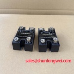
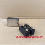
Before reconnecting the DC supply, verify the bridge terminals against the equipment schematic, inspect the mounting face for trapped debris, and confirm that the nameplate voltage boundary is compatible with the existing rectifier assembly. M50100THC1600-8701 is a SanRex / Crydom three phase rectifier module rated at Vrrm 1600 V and Id 100 A average rectified output current. These are Official Datasheet Specifications for the module and provide the first electrical limits to compare with the removed unit and the furnace power cabinet.
For maintenance planning, the stated 1200 A surge forward current applies to a 60 Hz, one cycle event, while the maximum forward voltage drop is 1.3 V at 100 A peak. The module also carries an Official Datasheet Specification of 2500 V AC isolation breakdown voltage for one minute. These ratings describe specific test conditions. They do not substitute for verification of the complete cabinet insulation path, cooling condition, protective coordination, or live operating waveform.
| Official specification | Published value | Integration relevance |
|---|---|---|
| Repetitive peak reverse voltage, Vrrm | 1600 V | Defines the stated repetitive reverse blocking boundary. |
| Average rectified output current, Id | 100 A, three phase bridge | Defines the stated average output-current rating. |
| Surge forward current, Ifsm | 1200 A, 60 Hz, one cycle | Supports assessment of short-duration fault exposure. |
| Maximum forward voltage drop, Vfm | 1.3 V at 100 A peak | Relevant to conduction-loss and thermal evaluation. |
| Isolation breakdown voltage, Visol | 2500 V AC for one minute | Relevant to insulation verification within the assembly. |
In a medium-frequency induction melting or hardening furnace, this module can be evaluated as part of the input or auxiliary three phase rectification path, subject to confirmation of the original circuit topology, bus voltage, current duty, cooling arrangement, and terminal layout. It is a diode rectifier module; gate-drive timing, dead-time selection, regenerative braking choppers, and bidirectional DC DC battery stages belong to surrounding controlled-power circuitry rather than to this product’s interface.
After a suspected line disturbance or a cleared downstream fault, begin with an isolated inspection of the bridge, fuse holder, cable lugs, and heatsink interface. Look for heat discoloration, loosened terminal hardware, contamination around conductive paths, or an uneven thermal compound imprint. With power removed and stored energy discharged according to the equipment procedure, compare diode conduction paths against the known circuit arrangement. A diode-test result can reveal a gross short or open condition, but it cannot establish full reverse-blocking performance at operating voltage.
The official 1200 A Ifsm figure is a one-cycle 60 Hz surge rating. It is not an operating-current allowance and should not be converted into a predicted number of fault events. Post-surge assessment should instead establish whether the semiconductor fuse operated within its published clearing characteristics, whether the bridge was exposed to continuing current, and whether reverse voltage can be reapplied without an unverified damaged path remaining in the cabinet.
Fuse coordination is a Design Consideration. Obtain the fuse manufacturer’s pre-arcing and total-clearing I2t data, then compare the applicable fault path with the module documentation and the actual upstream impedance. The purpose is to ensure that a fault is interrupted before semiconductor stress becomes unacceptable under the real fault conditions. The available official module data identifies the one-cycle surge current, but it does not provide a module-specific fuse I2t limit in the supplied specifications. A maintenance record should therefore retain the installed fuse part number, its data sheet revision, the observed fault location, and any protective-device replacement made during repair.
Reverse voltage deserves a separate check after a surge because a bridge can appear normal at low meter voltage while the operating circuit contains voltage transients, commutation stress, or line imbalance that a handheld meter cannot reproduce. Designers should verify peak reverse voltage at the installed DC-link and line conditions with appropriately rated measurement equipment. The measurement must be evaluated against the official 1600 V Vrrm rating and the complete system waveform, including any overshoot created by wiring inductance and switching equipment elsewhere in the cabinet.
Terminal connections need the same attention as the semiconductor. A loose lug can create localized heating, alter current sharing between incoming phases, and leave misleading evidence after a protection event. Use the module drawing and equipment service documentation to identify terminals and approved hardware. Mounting torque and terminal torque are Design Considerations unless stated in the original module drawing or equipment documentation; do not assign a torque value from a visually similar package.
Maintenance Note: Isolate the supply and verify that stored DC-link energy is discharged before loosening bridge terminals or removing the module from its heatsink.
When comparing an existing assembly with another listed device, M505013F can be reviewed as a separate product reference, but equivalence must be established from verified voltage, current, isolation, mechanical, terminal, and thermal documentation rather than from naming similarity.
M50100THC1600-8701 Thermal-Electrical Optimization: Diode Peak Reverse Recovery Current and Practical Tuning
Do not assign a reverse-recovery current or recovery-time value to M50100THC1600-8701 from the supplied official parameters. No Irrm, trr, softness factor, switching test circuit, or commutation-condition data has been provided for this module. Those properties vary with current, junction temperature, circuit inductance, and the external commutation conditions, so a numeric claim without the manufacturer’s switching data would not be reliable.
In a three phase bridge, a diode changes from conduction to blocking as the source phases commutate. The resulting waveform is shaped by the source, transformer leakage, wiring, DC-link behavior, and any active conversion stages connected downstream. Where the induction furnace supply includes high-frequency switching sections, service personnel should distinguish the mains or converter-front-end rectifier behavior from the waveform of inverter switching devices. Treating every observed ringing event as diode recovery can lead to an incorrect repair decision.
Reverse-recovery evaluation is a Design Consideration. Use an isolated, properly bandwidth-rated measurement method to inspect phase current and voltage at a known operating condition, then compare the result with the original equipment waveform or a verified healthy unit where available. Attention should be given to repetitive overshoot, abnormal phase asymmetry, and evidence that snubbers, busbars, cable terminations, or upstream protective parts have changed from their intended condition. The system engineer should verify peak margins against DC-link voltage during switching tests rather than relying on a generic numerical limit.
Minimizing parasitic loop inductance is an Engineering Recommendation when the goal is to suppress inductive overshoot during commutation. The routing, conductor geometry, capacitor location, shielding, and acceptable waveform result are system-determined. Do not modify suppression components only because a waveform looks different at a new probe position; first confirm the probe reference, bandwidth, isolation rating, and the operating state being captured.
The physical basis for semiconductor conduction involves charge carriers, a subject described in the reference material on the Hall effect and charge-carrier concentration measurement. That reference is useful background, not an official switching specification for this rectifier module. Likewise, communications wiring must be separated from power-noise investigation: an RS-485 differential bus can be present in furnace controls, but its interface characteristics do not define the recovery behavior of a power diode bridge.
For recurring commutation-related alarms, examine the sequence of symptoms rather than declaring one cause. A distorted phase waveform may indicate a source issue, a connection issue, a measurement issue, a changed suppression network, or an abnormal load state. Verify each candidate with the equipment schematic, measured waveform, and component documentation before replacing parts.
M50100THC1600-8701 Thermal-Electrical Optimization: Ensuring Uniform Heatsink Contact Pressure Practical Tuning
With the module removed, clean the heatsink contact area using a process approved for the equipment, inspect the surface for corrosion or raised damage, and examine the old thermal-interface pattern. A discontinuous imprint can indicate uneven clamping, contamination, warped surfaces, or an incorrect installation sequence. It does not by itself prove an internal semiconductor defect.
The supplied official parameters do not include a junction-to-case thermal resistance, baseplate construction, mounting-hole details, thermal compound thickness, or an approved mounting torque for this exact module. These values must be taken from the manufacturer mechanical drawing or the original equipment documentation before installation. Do not infer package dimensions, fastener size, or torque from photographs, inventory descriptions, or another bridge family.
Uniform contact pressure is a Design Consideration because it affects the thermal path from the module case into the heatsink. Apply thermal material using the approved maintenance process, place the module without sliding it across contaminated surfaces, and tighten hardware in a balanced sequence defined by the verified mounting instructions. Excessive force can distort a module or damage mounting hardware; inadequate force can degrade heat transfer. The correct value is installation-specific until confirmed by authoritative documentation.
During scheduled maintenance, inspect fan operation, clean blocked airflow paths, check that cabinet filters and ducting have not restricted cooling, and look for moisture or condensation evidence around high-current hardware. Contact-temperature monitoring can help detect a changing thermal condition when compared under comparable load and ambient conditions. A temperature increase should prompt inspection of airflow, heatsink cleanliness, terminal resistance, thermal interface condition, and actual electrical duty before assigning a single cause.
The maximum forward drop of 1.3 V at 100 A peak is an Official Datasheet Specification and is relevant to conduction behavior under that stated condition. It should not be used as a direct field acceptance threshold at another current, temperature, or waveform. The operating thermal result depends on the complete duty cycle, phase loading, cooling system, and the actual voltage-current characteristics under service conditions.
Where long-duration furnace availability is important, keep records of heatsink cleaning, thermal-interface renewal, terminal inspection, fan replacement, and measured operating conditions. This supports repeatable maintenance decisions without inventing a fixed module lifetime or a numerical failure prediction unsupported by field data.
Benchtop Waveform Tuning: Mitigating Stress via Short-Circuit Withstand Limits: Coordination of M50100THC1600-8701
A dead-short investigation should begin at the disconnected assembly level: identify the faulted branch, document the installed semiconductor fuse, inspect the bridge mounting and terminal condition, and confirm whether the protective device cleared before energy reached connected conductors or downstream components. The official 1200 A, 60 Hz, one-cycle Ifsm rating is a limited surge specification. It is not a guarantee of survival under every short circuit, repeated event, non-sinusoidal fault, or fault duration determined by a different supply frequency or protection system.
Fuse I2t coordination is therefore an Engineering Recommendation based on the actual protective device data and measured or calculated prospective fault conditions. The fuse supplier’s time-current and I2t curves must be read with the relevant voltage, fault-current, and installation assumptions. The system engineer should determine whether clearing energy, circuit inductance, transformer behavior, and conductor resistance are appropriate for the protected branch. No module-specific allowable clearing I2t figure is present in the supplied official specification set, so a numerical coordination claim for this bridge would be unsupported.
For a benchtop repair check, use controlled, documented test conditions appropriate to the furnace equipment. Verify phase connection order, confirm that no unintended conductive path remains across the DC output, and examine the current-sense and control interlock circuits before energization. A soft-start or precharge path, where fitted by the equipment manufacturer, should be evaluated as part of the original system architecture. It should not be bypassed to accelerate testing.
The 2500 V AC for one minute Visol rating is an Official Datasheet Specification for isolation breakdown testing. It does not certify the complete furnace cabinet, cable assembly, transformer, enclosure, or installation for any system safety standard. Insulation testing should follow the equipment manufacturer’s procedure and the applicable site safety requirements, with sensitive control electronics isolated or protected as instructed by those procedures.
For background on how modern high-voltage switching devices are evaluated in three phase conversion systems, see The 1200 V CoolSiC™ MOSFET Advantage in Three. That technical discussion concerns a different device technology and should be used as contextual reading only, not as a substitute specification or replacement decision for the M50100THC1600-8701 diode bridge.