



Content last revised on October 25, 2026
Inspect the gate-drive and power connections before installing an MBM150HS12A in a welder or induction-heating supply
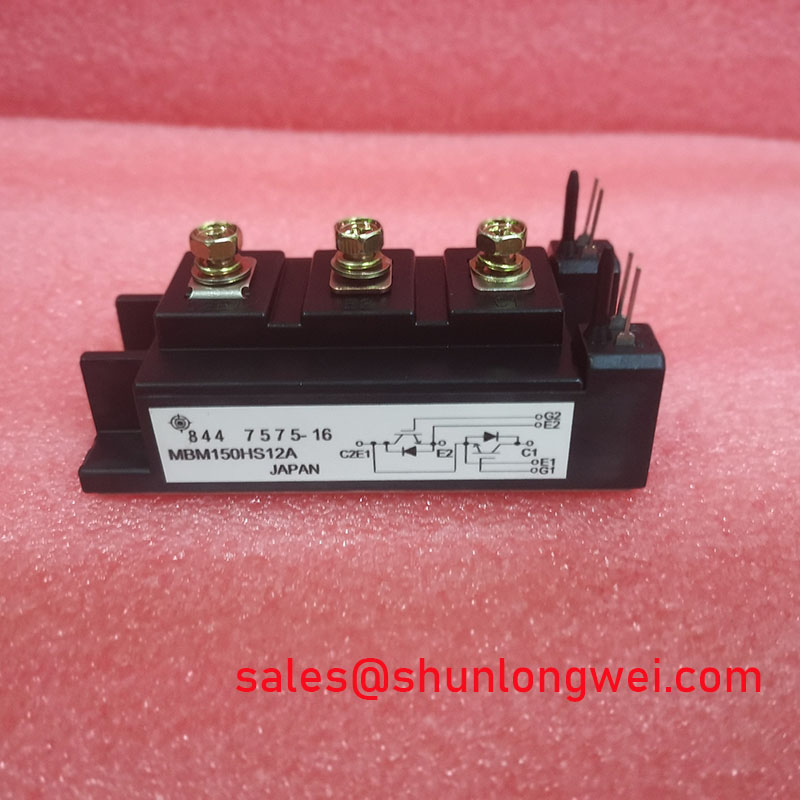
Confirm the module’s marking, terminal layout, and fit against the equipment documentation; do not infer pin polarity from a similar-looking package.
The Hitachi MBM150HS12A is specified as a 1200 V, 150 A IGBT module in a high-power isolated module package. These are official product ratings, not a complete application design: switching conditions, cooling, gate-drive requirements, and the equipment’s transient stresses all affect integration. Industrial inverter welders and medium-frequency induction-heating power supplies are potential compatibility contexts, subject to checking the original circuit and mechanical interfaces.
For incoming bench checks, use ESD precautions and begin with the device unpowered and isolated from the circuit. Verify terminal identification from the applicable module documentation before using a meter’s diode mode; readings depend on the measurement path and connected circuitry, so compare like-for-like devices under the same conditions rather than treating a single meter value as a pass/fail limit. 💡 Bench Tip: Record cold readings and test conditions so later comparisons are meaningful, and avoid applying insulation-test voltage across terminals unless the test points and procedure are specified for the module.
Preventing Spurious Faults: Gate Drive Resistance Calibration for MBM150HS12A Retrofits
When a legacy drive board is paired with an MBM150HS12A, first map the existing turn-on and turn-off gate paths, including any separate resistors, diodes, and driver output stages. The external gate resistance influences switching behavior: reducing it can increase switching speed and stress, while increasing it can reduce edge rate at the cost of switching loss. The appropriate balance depends on the actual circuit, not on the module’s voltage and current ratings alone.
Design Consideration: Treat the original resistor values as a starting reference, not proof of compatibility. Compare the replacement module’s gate requirements with the drive board’s output capability and inspect the gate-emitter return route. Keep gate and power-current paths distinct where the layout allows, and avoid routing sensitive gate wiring alongside high-current switching conductors. Clearance and insulation must follow the equipment’s applicable voltage and safety requirements.
During commissioning, observe gate-emitter and collector-emitter waveforms with suitable isolated measurement methods. Look for unwanted ringing, uneven switching, or abnormal overshoot, then adjust the turn-on and turn-off paths in controlled increments while monitoring device temperature and switching behavior. If a fault appears only under load, check driver supply stability, connector condition, and switching-loop layout before attributing it to the module.
For a cross-reference review, compare the circuit and mechanical requirements of the SKM150GAL12T4 independently; its presence here does not establish it as a drop-in substitute. A substitution decision requires matching terminal arrangement, gate characteristics, thermal interface, and the original equipment’s operating conditions.
MBM150HS12A Thermal-Electrical Optimization: Heatsink Flatness and Thermal Grease Tuning
Before fastening the module, inspect the heatsink contact area for debris, damage, and unevenness. A poor interface can impede heat transfer even when the cooling system appears operational. Clean the mating surfaces using a method appropriate to the equipment, and apply thermal interface material as a controlled, uniform layer according to the module and interface-material instructions.
Use the specified mounting hardware and tightening procedure for the actual module. A diagonal, staged tightening sequence is a general assembly consideration that can help distribute pressure, but it does not replace the manufacturer’s torque specification. Do not assume a baseplate shape, permitted flatness, or thermal-grease thickness from the package category alone; those details must come from the relevant mechanical documentation. Excessive or uneven clamping can damage the assembly.
Operating temperature depends on conduction, airflow, switching losses, and duty cycle. A broad switching-frequency range such as 2 kHz to 16 kHz cannot be treated as an approved operating range for this particular module without supporting ratings and conditions. If evaluating a power supply across different switching frequencies or high ambient temperatures, monitor case or heatsink temperature under representative load and check the complete cooling path, including airflow obstruction and fan performance. Apply any required derating from the device documentation and system thermal analysis.
For an insulation check, identify the intended test terminals and permitted test conditions before applying a tester. The module’s 1200 V rating is not an insulation-test voltage or a statement of system creepage and clearance. Those requirements depend on the equipment’s working voltage, pollution environment, altitude, and applicable standards.
MBM150HS12A Operational Boundaries: Static and Dynamic Current Distribution
In a parallel-device arrangement, current balance must be assessed both during steady conduction and during switching. Similar power-path impedances help reduce static imbalance, while matched gate-drive routing and return paths support more consistent dynamic behavior. Keep conductor geometry as symmetrical as practical and review the complete busbar, emitter, and gate connections rather than comparing the module ratings in isolation.
A positive temperature coefficient of on-state voltage is sometimes used in current-sharing analysis, but no specific VCE(sat) characteristic or temperature coefficient is established here for the MBM150HS12A. Do not rely on that behavior as a guaranteed balancing mechanism. When evaluating parallel operation, use the device’s documented electrical curves and test the assembled circuit across its intended load and thermal conditions.
Use current measurements appropriate to the switching environment and compare branch waveforms at equivalent points. Current-sense amplifier approaches are described in the ADI current-sense amplifier resource; magnetic sensing principles, including GMR, are summarized in this GMR reference. These are measurement approaches, not claims about sensors included in the module.
For fault analysis, record the operating point, probe location, and test setup alongside observed waveforms. A current imbalance may arise from layout, gate timing, device variation, or measurement placement; comparing branches under matched conditions helps narrow the investigation without assuming a single cause. The Field Engineer’s Handbook provides related troubleshooting and reliability context.
Transient Dynamics and Electrical Design: Dynamic Braking Chopper Operation
A braking chopper evaluation begins with the drive topology: determine whether the equipment uses a braking switch within the assembly or a separate external device, and identify the resistor and DC-link connection from the schematic. The MBM150HS12A ratings alone do not establish that it contains a braking IGBT or that it is suitable for a particular chopper circuit.
For a regenerative load, the braking system must manage energy returned to the DC link during deceleration. Selection of the switching device and resistor depends on the motor and load, deceleration profile, DC-link limits, repetition rate, and thermal environment. Those system-level conditions determine the required energy and power handling; they cannot be derived from the module’s 1200 V and 150 A ratings alone.
During troubleshooting, inspect the chopper command and switching waveform alongside the DC-link trend and resistor condition. Check for loose power connections, damaged insulation, or evidence of overheating, then compare measured behavior with the equipment’s specified thresholds. Keep transient-current loops compact as a design consideration, and verify switching peaks against the system limits using an appropriate measurement setup. Do not assume a MOV or other surge suppressor can replace correctly rated braking components; protection coordination must suit the actual DC-link circuit.