Content last revised on October 10, 2026
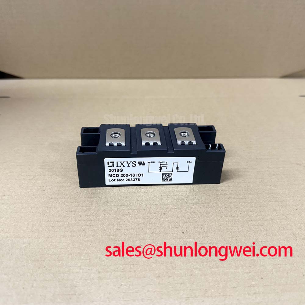
Assembly Integrity & Layout Architecture: Implementing Junction-to-Heatsink Heat Dissipation for MCD132-18IO1
Check heatsink flatness, mounting-face cleanliness, and terminal alignment before tightening the module. As a Design Consideration, an uneven interface can impair heat transfer even when the heatsink itself remains relatively cool. Inspect the thermal compound spread for interrupted contact or excessive accumulation, and avoid using mounting screws to pull a misaligned assembly into position.
Junction-to-case thermal resistance, R_th(j-c), describes only part of the heat path. Interface resistance and heatsink performance remain separate integration variables. Use the manufacturer’s thermal-resistance values under their stated conduction conditions when assessing dissipation; a case-temperature measurement alone does not establish junction temperature. No particular baseplate material should be assumed from the external package designation.
For assembly control, record the mounting fastener specification, tightening sequence, and manufacturer-authorized torque alongside the inspection result. Power-terminal tightening and heatsink mounting are different operations. Support connected conductors so that their weight or misalignment does not load the module terminals.
💡 Bench Tip: Disconnect parallel circuit paths before diode-mode testing, and compare readings with a known-good module using the same instrument, probe polarity, and cold-state conditions.
Insulation assessment requires a separate test plan. Review the specified insulation-test voltage, duration, and terminal-to-baseplate arrangement before testing, and keep gate circuitry and connected electronics outside inappropriate test paths. A handheld resistance check can identify gross leakage but cannot establish compliance with an insulation withstand specification.
Transient Dynamics & Electrical Design: ITSM Safety Derating for Repetitive Events on MCD132-18IO1
Match the actual surge waveform to the conditions attached to ITSM before assessing fault tolerance. A non-repetitive surge rating is not a repetitive starting-current allowance. Where the datasheet specifies a sinusoidal half-cycle of 10 ms, evaluate that rating with its stated initial junction temperature and reverse-voltage conditions, rather than extending it to a different pulse shape.
As a Design Consideration, semiconductor fuse coordination should compare the module’s applicable I²t limit with the fuse’s total clearing I²t under the prospective fault conditions. Pre-arcing data alone does not describe the complete interruption event. Repeated starts also require a thermal assessment covering the interval between events and the temperature present before reverse voltage is reapplied.
For maintenance procurement, MCD312-18IO1 is a related IXYS part to evaluate, not an established drop-in replacement. Compare its circuit arrangement, terminal positions, thermal requirements, and trigger characteristics before changing the approved bill of materials.
| Selection checkpoint | MCD132-18IO1 | MCD312-18IO1 |
|---|---|---|
| Manufacturer | IXYS | IXYS |
| Specified product current | 132 A; verify rating conditions | Consult datasheet |
| Package designation | TO-240AA | Consult datasheet |
| Blocking voltage, surge limits, and insulation test | Consult datasheet | Consult datasheet |
| Replacement acceptance | Match existing schematic and mechanical drawing | Requires electrical and mechanical comparison |
When evaluating a high-voltage three-phase motor solid-state soft starter, designers should verify the required phase-leg arrangement and blocking-voltage capability against the actual power circuit. The supplied description “Standard Industrial Rating” does not establish a numerical voltage limit.
Benchtop Waveform Tuning: Mitigating Stress via Gate Trigger Current Dynamics on MCD132-18IO1
Measure the gate pulse at the module’s gate and corresponding cathode connection rather than only at the driver output. As an Engineering Recommendation, inspect delivered current, pulse duration, and ringing under representative loading, then compare them with the manufacturer’s trigger and gate-power limits. Keep the gate-current return path compact to reduce waveform distortion from parasitic inductance.
IGT and VGT describe triggering conditions; latching current and holding current describe different stages of conduction. A pulse train may support reliable firing when load current develops slowly, but its amplitude, repetition, and duration must respect the module’s gate limits. Gate drive does not turn off a conventional thyristor, so transistor-style dead-time tuning is not a substitute for checking commutation.
Reverse-recovery behavior also deserves attention when assessing current transfer. ROHM’s fast-recovery diode resources and the explanation of reverse-recovery charge and recovery behavior provide general context, not MCD132-18IO1 specifications. Likewise, Wide Bandgap Revolution offers background on different power-device technologies, not evidence of this module’s service life. For bench acceptance, retain the measured gate waveform, cold-state electrical readings, and terminal identification with the inspection record.