Content last revised on October 14, 2026
Transient Dynamics & Electrical Design: Reverse Recovery Charge Temperature Coefficient on MCD312-18IO1
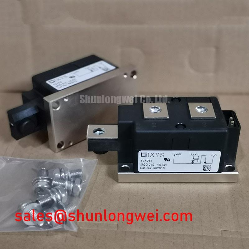
Isolate the power assembly, verify that stored energy has discharged, and match the module’s terminal markings to the equipment schematic before disconnecting the busbars. For an IXYS MCD312-18IO1, record the power-terminal arrangement and gate wiring as carefully as the part number: a mechanically compatible replacement can still have a different internal circuit.
The supplied product specifications identify a 520.0 A current rating and a TO-240AA package. Confirm the numerical blocking-voltage rating in the manufacturer’s datasheet. Consult the manufacturer’s datasheet for the electrical rating conditions, internal circuit, recovery characteristics, thermal limits, and tightening torques before approving installation. The MCD thyristor/diode configuration also needs to be distinguished from a dual-thyristor circuit during replacement assessment.
Capture diode current and device voltage through the actual commutation interval when investigating an abnormal switching transient. As a Design Consideration, reverse-recovery peak current, recovery duration, and recovered charge must be assessed together with junction temperature, forward current, and the imposed current-change rate. Recovery duration alone does not establish soft recovery, and a ringing waveform does not identify a defective module without checking the surrounding circuit.
Keep the voltage probe connection compact and establish the current probe’s polarity before comparing traces. Evaluate cold and thermally stabilized operation under repeatable load conditions. Changes in peak reverse current or voltage overshoot can reflect temperature, commutation conditions, or connection inductance; the comparison should separate those influences rather than assigning every change to the semiconductor.
For protection coordination, compare the semiconductor’s datasheet I²t withstand conditions with the fuse manufacturer’s total-clearing I²t at the applicable circuit voltage and prospective fault current. This is a Design Consideration, not a fuse selection based solely on the module’s current label. Check the main-terminal connections against the circuit drawing, including the return path used by the gate circuit.
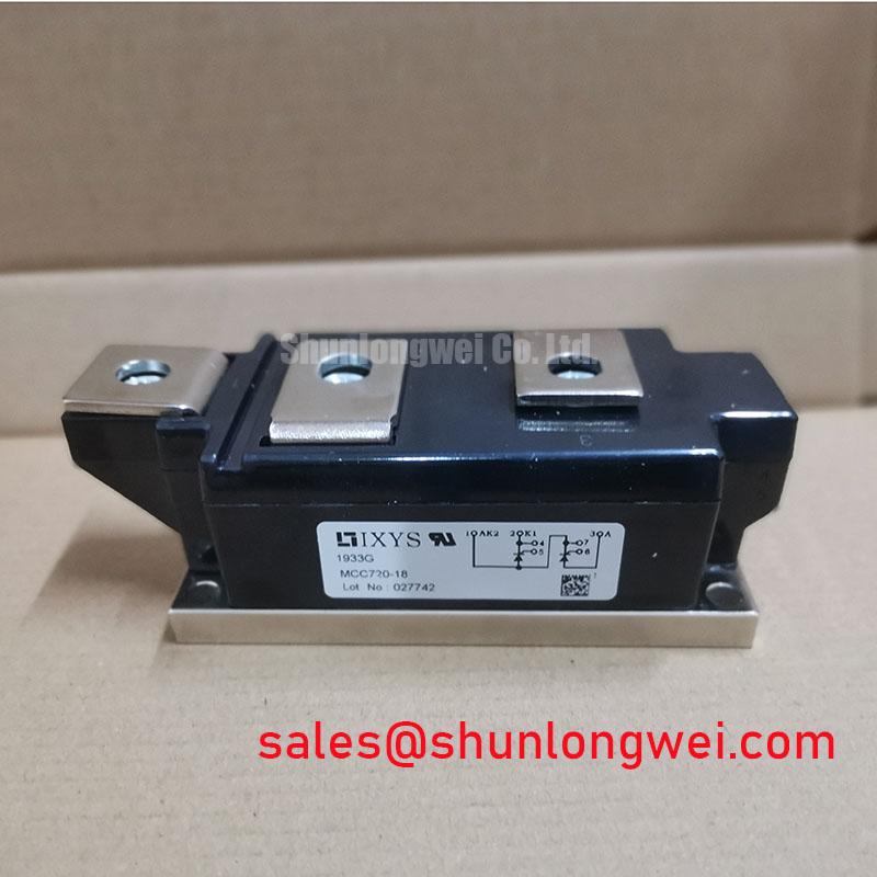
When reviewing the power assembly, MCC162-18IO1 can be considered as a related thyristor-module reference within the wider rectifier topology, not as an automatically interchangeable component. Gate-drive arrangement, internal circuit, and commutation requirements determine its relevance. Likewise, dead-time and non-overlap concepts apply to controlled switching stages; they do not replace the current extinction and recovery conditions required for thyristor commutation.
MCD312-18IO1 Thermal-Electrical Optimization: Ensuring Uniform Heatsink Contact Pressure Practical Tuning
Inspect the heatsink mating surface and the removed thermal-interface imprint before cleaning the assembly. Uneven transfer, debris, or local surface damage warrants investigation because mounting pressure must establish thermal contact without distorting the module. Use the specified mounting sequence and separate the requirements for base mounting from those for electrical-terminal tightening.
As a Design Consideration, junction-to-case thermal resistance describes only part of the heat path. Interface condition, heatsink performance, airflow, and neighboring heat sources affect the installed temperature. For intermittent loading, the manufacturer’s transient thermal-impedance curves should be applied using their stated pulse and initial-temperature conditions; steady-state thermal resistance alone does not characterize the peak junction temperature during a short overload.
Track case temperature and terminal temperature at consistent measurement locations and comparable loads. A warmer connection can justify checking contact condition, conductor support, and tightening records, but it does not establish a single failure cause. Set inspection intervals from the equipment duty, contamination exposure, and observed thermal trend rather than assigning an unsupported replacement interval to the thermal material.
Maintenance Note: Monitor terminal-temperature trends and keep the heatsink airflow path clear before increasing the operating load.
For replacement assessment, compare MCC200-14IO1 against the complete electrical and mechanical requirements, including its different circuit configuration, rather than treating package resemblance as equivalence. In environments with temperature cycling, an Engineering Recommendation is to check for condensation before energization and correct the enclosure conditions responsible for moisture accumulation.
MCD312-18IO1 Operational Boundaries: Evaluating Harmonic Current Injection and Line Filter Limits
Measure input current, line voltage, and DC output while changing the firing command under controlled load conditions. As a Design Consideration, the relationship between firing angle and DC output depends on bridge configuration, source impedance, load behavior, and whether current remains continuous. A transfer curve for a fully controlled bridge should not be applied unchanged to a mixed thyristor/diode arrangement.
Delayed conduction changes the input-current waveform and can increase reactive-power demand, but filter loading must be assessed from the measured spectrum and the filter’s own ratings. Designers evaluating the module for a medium-frequency induction melting or hardening furnace should verify its role in the supply rectifier separately from the downstream inverter’s operating requirements.
Where isolated sensing supports the control loop, Broadcom’s isolated amplifiers and current sensors provide relevant component-level references. Their common-mode transient performance belongs to the sensing circuit, not to the MCD312-18IO1 specification. Compare sensor output and firing commands during commutation to distinguish measurement disturbance from actual current variation.
Use the Field Engineer’s Handbook to organize repeatable troubleshooting records. Retain waveform captures, load conditions, temperature measurements, and terminal-service observations so that subsequent maintenance checks address the same operating point.