Content last revised on October 8, 2026
Field Diagnostics and Commissioning: Voltage Sharing and RC Damping
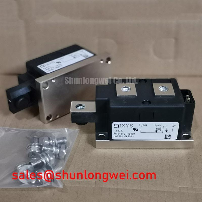
MCD312-14IO1 | IXYS | Dual Thyristor Module | 1400 V rated voltage | 520 A rated current | TO-240AA package. These are official specification values; circuit suitability depends on the equipment design and operating conditions.
Measure the cold-state resistance across the disconnected power terminals, then compare each control-terminal path with the equipment schematic and a known-good assembly. Isolate the module from parallel circuit paths before interpreting a low resistance reading. Inspect terminal hardware and the heatsink interface for looseness, discoloration or uneven contact. The 1400 V and 520 A ratings are official specifications for MCD312-14IO1, not measured commissioning results.
If the equipment connects modules in series, capture voltage across each module during controlled switching. Unequal transient voltage may call for examination of the existing RC sharing and damping network, trigger timing and wiring geometry. As a Design Consideration, select any changes to snubber resistance or capacitance from measured waveforms and the system’s voltage margins; the module rating alone does not determine those values. Where a series reactor is present, inspect its connections and compare its measured behavior with the equipment design before changing it.
A grid-tied static var compensator or thyristor-switched capacitor bank is a possible compatibility assessment, not a confirmed application for every MCD312-14IO1 installation. Trace the actual power and trigger paths first. IEC’s IEC 60747-6 semiconductor-device standard for thyristors provides terminology for evaluating thyristor characteristics; it does not establish that this particular assembly has passed a system-level test.
MCD312-14IO1 Short-Circuit Protection and Fuse Coordination
Check the installed semiconductor fuse designation against the equipment protection schedule, then inspect the module and adjacent bus connections before resetting a fault. A cold-state multimeter check can reveal an obvious short, but it cannot establish remaining surge capability. Do not treat the 520 A official current rating as a fuse-clearing or short-circuit-withstand rating.
For fuse coordination, compare the fuse manufacturer’s total clearing I²t at the applicable voltage and prospective fault current with the module’s documented non-repetitive surge and I²t limits under their stated conditions. No such limits or fuse coordination table are supplied in the stated specifications, so a numerical coordination result cannot be established here. Fault interruption also depends on the upstream supply and protective arrangement; no fuse choice can be inferred to guarantee damage-free clearing.
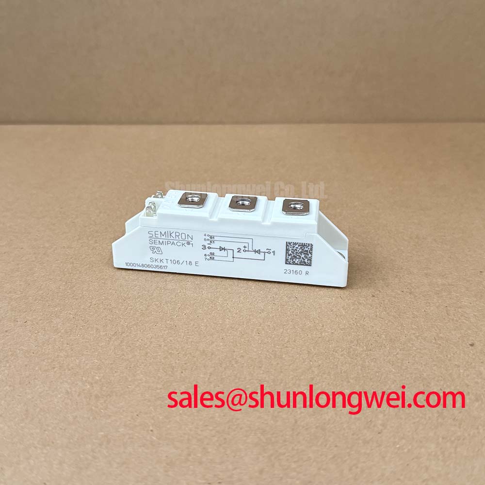
During a replacement assessment, compare the original circuit diagram, terminal arrangement, mounting envelope and protection schedule rather than matching current ratings alone. TT500N18KOF is a separate part for cross-model evaluation, not an established drop-in substitute. In a related rectifier or switching stage, SKKT 106B14E likewise requires its own topology and rating check.
Mechanical Mounting and Thermal Contact for the TO-240AA Package
Inspect the heatsink footprint and mounting holes for burrs, contamination and distortion before seating the TO-240AA package. Check that the replacement sits flat without using the terminal fasteners to pull it into position. Apply thermal interface material in a uniform layer suited to the approved assembly procedure, then tighten the mounting hardware in the sequence specified for the equipment and fasteners.
Field Alert: Do not assign a mounting torque from bolt size alone; use the approved module and equipment instructions so the package is not distorted.
As a Design Consideration, thermal resistance depends on contact quality, interface material and cooling conditions as well as the device itself. A numerical junction-to-case thermal resistance or torque value is not included in the supplied official specifications, so neither should be assumed. During controlled commissioning, compare case-temperature trends and terminal temperatures with the equipment’s established reference data. A local hot spot may warrant checking contact pressure, current sharing and connections before attributing it to the module.
Benchtop Waveform Tuning: Commutation Voltage Stress
Capture voltage across the switching path during a controlled commutation test and look for overshoot, ringing or unexpected retriggering. Keep the probe connection short and use instrumentation appropriate to the circuit voltage. Compare the observed peak with the 1400 V official voltage rating under the relevant test conditions; assess the required operating margin from the complete system design.
As a Design Consideration, reducing parasitic loop inductance and checking the installed damping network can help limit commutation overshoot. Adjustments belong to the equipment’s measured waveform and protection design, not to an assumed universal snubber value. Where the associated circuit includes a diode, evaluate its reverse-recovery behavior using that diode’s documentation and captured current waveform; no diode recovery specification is established for MCD312-14IO1 by the supplied data.
Inspect trigger wiring for coupled noise while reviewing the waveform. The discussion of Evolution of Negative Off-Bias Gate Drive Circuits concerns gate-drive techniques in other switching-device contexts and should not be applied as a thyristor trigger prescription. Finish the bench check by recording the measured peak voltage, test conditions and installed damping configuration for comparison during the next service visit.