Content last revised on October 5, 2026
MCD255-14IO1 Thermal-Electrical Optimization: Gate Trigger Current and Temperature-Dependent Practical Tuning
| Specification | Official Value |
|---|---|
| Manufacturer | IXYS |
| Product Category | Thyristor/Diode Module |
| Rated Voltage | 1400.0 V |
| Rated Current | 250.0 A |
| Package | TO-240AA |
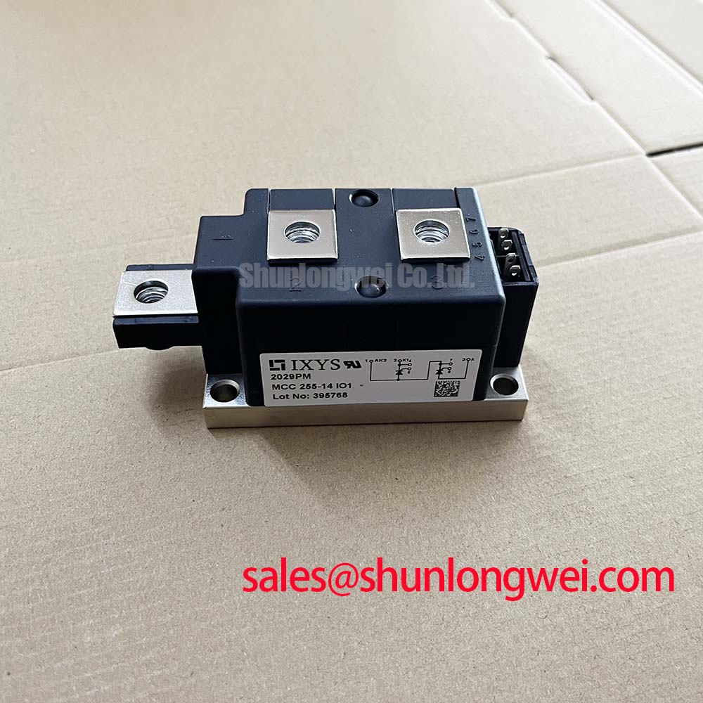
Probe the gate trigger wiring and compare the firing waveform at the module terminals with the controller output before replacing the MCD255-14IO1. A distorted or delayed pulse can result from excessive lead inductance, poor return routing, a loose terminal, or a trigger circuit that is not matched to the thyristor assembly.
The module is specified at 1400.0 V and 250.0 A in a TO-240AA package. Gate current, pulse width, rise time, holding behavior, and temperature dependence must be taken from the applicable IXYS technical documentation and checked against the installed firing circuit. Do not infer a gate pulse value from the module’s load-current rating.
For a high-voltage three-phase motor solid-state soft starter, keep gate and power-current routing physically controlled, with short trigger returns and clear separation from high di/dt conductor paths. A multi-pulse firing method may be evaluated where the control system requires improved triggering across temperature, but the pulse sequence remains a system design decision. Use an oscilloscope with an appropriately rated differential probe to compare all controlled legs under cold and thermally stabilized conditions.
Thermal inspection should include heatsink cleanliness, interface material condition, clamping uniformity, and terminal temperature balance. Maintenance Note: isolate the equipment before retightening terminals or disconnecting any trigger wiring, then verify airflow and contact temperature during a controlled load test.
MCD255-14IO1 Operational Boundaries: Evaluating Type-2 Coordination and Sub-Cycle Fault Limits
Record the semiconductor fuse identification, fuse manufacturer’s clearing data, and the module’s applicable surge-current and I²t ratings before approving a Type-2 coordination review. A 1400 V, 250 A module rating alone cannot establish short-circuit protection or guarantee zero mechanical damage during a dead-short event.
The engineering check compares the fuse clearing energy with the thyristor and diode withstand limits stated for the exact device revision and operating condition. The fuse must also be suitable for the actual prospective short-circuit current, supply arrangement, fault location, and available discrimination with upstream protection. If the relevant coordination table is unavailable, the correct action is to obtain the original technical data rather than substitute a nominal fuse rating.
Inspect the busbar joints, pressure interfaces, and terminal hardware for discoloration, looseness, or uneven heating after a protection trip. The TO-240AA mounting arrangement should follow the mechanical instructions associated with the heatsink and hardware used in the equipment. Mounting torque is not established by the electrical ratings supplied here, so it should be taken from the approved mechanical assembly documentation.
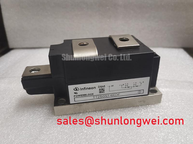
For field replacement planning, the TT500N18KOF can be evaluated as a separate module option only after voltage, current, package, gate characteristics, thermal interface, and protection coordination have been compared by the system designer.
Preventing Spurious Faults: High-Frequency Switching Loss Dissipation Guidelines for MCD255-14IO1
Capture the commutation waveform at the power terminals and inspect reverse-recovery current, voltage overshoot, ringing, and thermal rise before attributing a nuisance trip to the module. A three-phase soft starter normally operates differently from a high-frequency inverter, so switching-loss assumptions must follow the actual topology and firing strategy.
Reverse-recovery peak current and recovery time are device and circuit parameters that require the applicable IXYS curves or test conditions. They should not be estimated from the 250.0 A current rating. Minimize stray inductance in the commutation loop, maintain a controlled gate-return path, and verify peak voltage against the system’s insulation and semiconductor limits during switching tests.
Where surge suppression is required, the selected network must be coordinated with the line voltage, transient energy, repetition rate, and insulation system. A TVS device is one possible protection element; its operating principle is described in this external TVS diode reference. Component selection and EMC performance remain system-level responsibilities, and the module itself should not be represented as independently certified for complete equipment emissions compliance.
Use thermal imaging or bonded sensors to compare phase temperatures under matched load conditions. Uneven readings may justify checking gate timing, current sharing, heatsink contact, airflow, and terminal resistance as a combined diagnostic path.
Preventing Spurious Faults: Power-Factor Degradation and Harmonic Mitigation Guidelines for MCD255-14IO1
Measure line current and voltage at the soft-starter input while recording firing-angle behavior, motor loading, bypass status, and phase balance. This identifies whether poor power factor or harmonic current is associated with the controlled conduction interval, upstream impedance, motor conditions, or an unrelated supply disturbance.
A thyristor soft starter changes the effective conduction period during acceleration, which can increase reactive demand and waveform distortion compared with a bypassed motor connection. The relationship between firing angle, motor current, displacement power factor, and harmonic content must be evaluated with the complete motor and supply model. It cannot be derived from the 1400.0 V voltage rating or the 250.0 A current rating alone.
Use a power-quality analyzer to capture current distortion during ramp-up, steady operation, and bypass transition. If correction equipment, line reactors, filters, or passive harmonic mitigation are considered, verify resonance risk, fault-current contribution, thermal loading, and compatibility with the soft-starter control sequence. The Precision Gate Drive Design resource provides related engineering context for evaluating trigger integrity and switching behavior.
For long-term maintenance, trend phase current balance, heatsink temperature, airflow condition, and terminal temperature during comparable production cycles. Changes in these measurements provide a practical basis for deciding whether the firing circuit, mechanical assembly, protection network, or wider power system requires further testing.