Content last revised on October 8, 2026
ME601615 Thermal Electrical Optimization and Short Circuit Coordination
Begin a service inspection by isolating the power stage, confirming that the equipment is fully discharged, and comparing the installed module marking with the required electrical boundary. The SanRex ME601615 is identified in the supplied product data as a Thyristor / Diode Module with a rated voltage of 1600.0 V and a rated current of 150.0 A. Its listed package is SanRex Power Module.
These three values are Official Specification data for product identification. They are not a complete short circuit coordination table. The available product information does not provide a semiconductor fuse I²t value, a thyristor short circuit withstand time, a diode surge current rating, or a manufacturer approved fuse pairing. A replacement assessment should therefore compare the original equipment documentation with the complete SanRex datasheet before energizing the converter.
For a medium frequency induction melting and hardening furnace, the module may operate within a rectifier, controlled conversion, or commutation stage depending on the original topology. The service engineer should first document the circuit position, terminal arrangement, cooling path, gate or control connections, and the protective device fitted upstream. The 1600.0 V voltage rating and 150.0 A current rating help establish the component identity, but they do not by themselves define the permissible operating point of the complete furnace power circuit.
Short circuit protection should be evaluated as a coordinated system function. The selected semiconductor fuse must clear fault energy before the module exceeds the withstand limits stated in the applicable manufacturer documentation. Because no official I²t coordination data has been supplied for ME601615, the fuse rating should not be inferred from the 150.0 A nameplate value. Engineers should obtain the original fuse specification, prospective fault current, DC link or AC source conditions, and protective clearing characteristics, then verify coordination through the equipment manufacturer’s approved protection data.
Terminal work deserves the same attention as electrical calculations. Clean the contact surfaces according to the equipment service procedure, inspect for discoloration or signs of overheating, and confirm that busbar alignment does not impose mechanical stress on the power module. The system integrator should verify terminal polarity and control connections from the original SanRex documentation rather than assuming a universal layout for every SanRex Power Module.
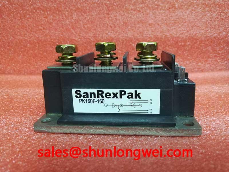
For field replacement planning, the FRS200CA100 can be reviewed as a separate device in the same sourcing discussion. It should not be treated as an automatic substitute for ME601615. Voltage class, current behavior, terminal geometry, thermal interface, gate or control requirements, and the original equipment approval must all be checked independently.
Safety Interlock Note: Disconnect and verify the absence of hazardous voltage before removing terminals or inserting a replacement module.
Preventing Spurious Faults and Reviewing Reverse Recovery Requirements
When a furnace converter produces irregular commutation, unexpected overcurrent trips, or abnormal switching noise, begin by recording the operating condition and checking the known good signal path. Inspect the module terminals, gate or control wiring, snubber network, current sensors, and protective interlocks before assigning the fault to reverse recovery. A single symptom can result from several interacting circuit conditions.
ME601615 is identified by the supplied official data as a 1600.0 V, 150.0 A SanRex Thyristor / Diode Module. The supplied parameter set does not include reverse recovery charge, reverse recovery peak current, reverse recovery time, softness factor, forward voltage, leakage current, or switching loss curves. Those values must be taken from the applicable manufacturer datasheet or technical drawing. They should not be estimated from the voltage and current ratings.
In a medium frequency induction heating supply, diode commutation behavior can influence current transfer, voltage overshoot, conducted noise, and thermal loading in adjacent switching devices. The correct engineering method is to identify the commutation path, measure the actual current and voltage waveforms under the intended operating condition, and compare the observed peak values with the component and system limits. The measurement setup should use a suitable high voltage probe, an appropriately rated current probe, and a carefully arranged reference connection so that probe loop inductance does not create misleading ringing.
Gate or control timing should also be checked against the original control design. The available information does not state the required gate current, gate trigger voltage, latching current, holding current, or permissible trigger pulse width for ME601615. Designers should verify these requirements from the SanRex documentation and confirm that the driver can maintain reliable triggering across the expected temperature and load range. A control signal that appears correct at the driver output may still be unsuitable at the module terminals if wiring impedance, isolation, or reference placement is incorrect.
The official SanRex website remains the appropriate manufacturer reference for available power semiconductor module documentation: SanRex Sansha Electric Power Semiconductor Modules. Datasheet revisions should be checked before a production replacement is released, particularly where the original furnace design uses a specific fuse, snubber, gate transformer, or firing controller.
A separate device such as PK55FG120 may appear in the wider power topology as a rectification or auxiliary stage reference, but its presence does not establish electrical interchangeability with ME601615. The complete circuit function must be traced from the schematic and verified against the original bill of materials.
Transient Dynamics and Baseplate Thermal Interface Evaluation
Before mounting ME601615, inspect the heatsink surface, module base, mounting holes, busbar position, and thermal interface condition. The product data identifies the enclosure as a SanRex Power Module, but it does not provide junction to case thermal resistance, case to heatsink thermal resistance, maximum junction temperature, baseplate flatness, recommended mounting torque, or thermal compound thickness. Those installation values must be confirmed from the relevant SanRex mechanical and thermal documentation.
Thermal evaluation should begin with the actual loss sources in the furnace converter. Conduction loss, commutation loss, control timing, load current, switching frequency, ambient temperature, airflow, and heatsink performance all affect junction temperature. The official 1600.0 V and 150.0 A ratings identify the electrical class of the component; they do not represent a universal continuous operating point under every cooling condition.
Uniform mechanical contact is important because uneven pressure can increase thermal resistance or stress the package. The heatsink should be clean and free of burrs, contamination, and raised metal around mounting holes. Apply the thermal interface material in accordance with the manufacturer’s installation instructions. If those instructions are unavailable, the equipment builder should obtain them before installation rather than applying a generic quantity or torque value.
During commissioning, monitor the relevant case or heatsink temperature while recording load current, operating frequency, cooling conditions, and fault history. A temperature increase may reflect insufficient contact, excessive electrical loss, restricted airflow, sensor placement, or an operating point outside the original design envelope. Verification should compare measured behavior with the complete SanRex thermal curves, not with the 150.0 A rating alone.
Transient testing should be performed after the physical installation has been verified. Minimize unnecessary stray inductance in the high current commutation loop to reduce voltage overshoot, then confirm peak voltage and current with appropriately rated instrumentation. The system engineer should compare measured transient margins with the 1600.0 V device rating and the limits of every connected component. This is an Engineering Recommendation for system validation, not an additional factory specification for ME601615.
For wider design background on high speed power semiconductor behavior, engineers may consult Wide Bandgap Revolution. The article is a general technical reference and does not replace the SanRex documentation for this silicon thyristor and diode module.
ME601615 Operating Boundaries, Power Factor, and Harmonic Assessment
Evaluate the complete AC to DC or controlled conversion stage from the furnace schematic before judging power factor or harmonic performance. ME601615 is listed with a 1600.0 V rated voltage, a 150.0 A rated current, and a SanRex Power Module package. The supplied product data does not specify firing angle range, repetitive peak current, surge current, commutation characteristics, power factor, harmonic current limits, or an approved operating waveform.
In a controlled rectifier, changing the firing command changes the relationship between source voltage, load current, reactive power, and harmonic current. The actual result depends on the supply impedance, transformer arrangement, DC side inductance, load profile, firing controller, commutation overlap, and whether the furnace uses a rectifier inverter combination. Engineers should measure line voltage and line current together at representative furnace conditions instead of deriving performance from the module’s voltage and current ratings.
When the firing angle is varied across the controller’s permitted range, record displacement power factor, true power factor, current distortion, DC output behavior, and protection events. The controller’s nominal command angle should not be treated as the measured electrical angle without confirming the control reference and commutation interval. Any angle limits must come from the original converter design or the applicable SanRex application documentation.
Harmonic mitigation is a system-level decision. Possible measures can include source impedance review, phase arrangement, passive or active filtering, firing control adjustment, and coordination with the furnace transformer. The correct solution depends on measured harmonic content and the limits imposed by the installation standard or utility connection agreement. ME601615 itself should not be described as independently compliant with an EMC or power quality standard.
For maintenance teams, a useful diagnostic record includes the module identification, measured line and load waveforms, cooling conditions, protection settings, fuse details, terminal inspection results, and the operating state at the time of the event. This record supports a controlled comparison between the installed unit and the original equipment documentation. It also helps distinguish a module issue from a firing controller, sensor, transformer, fuse, or commutation problem.
The system integrator should confirm all terminal definitions, gate requirements, cooling data, fuse coordination information, and mechanical installation limits from the current manufacturer documentation before releasing the furnace for service.