Content last revised on September 27, 2026
Transient Dynamics & Electrical Design: Baseplate Thermal Resistance on TT142N16KOF
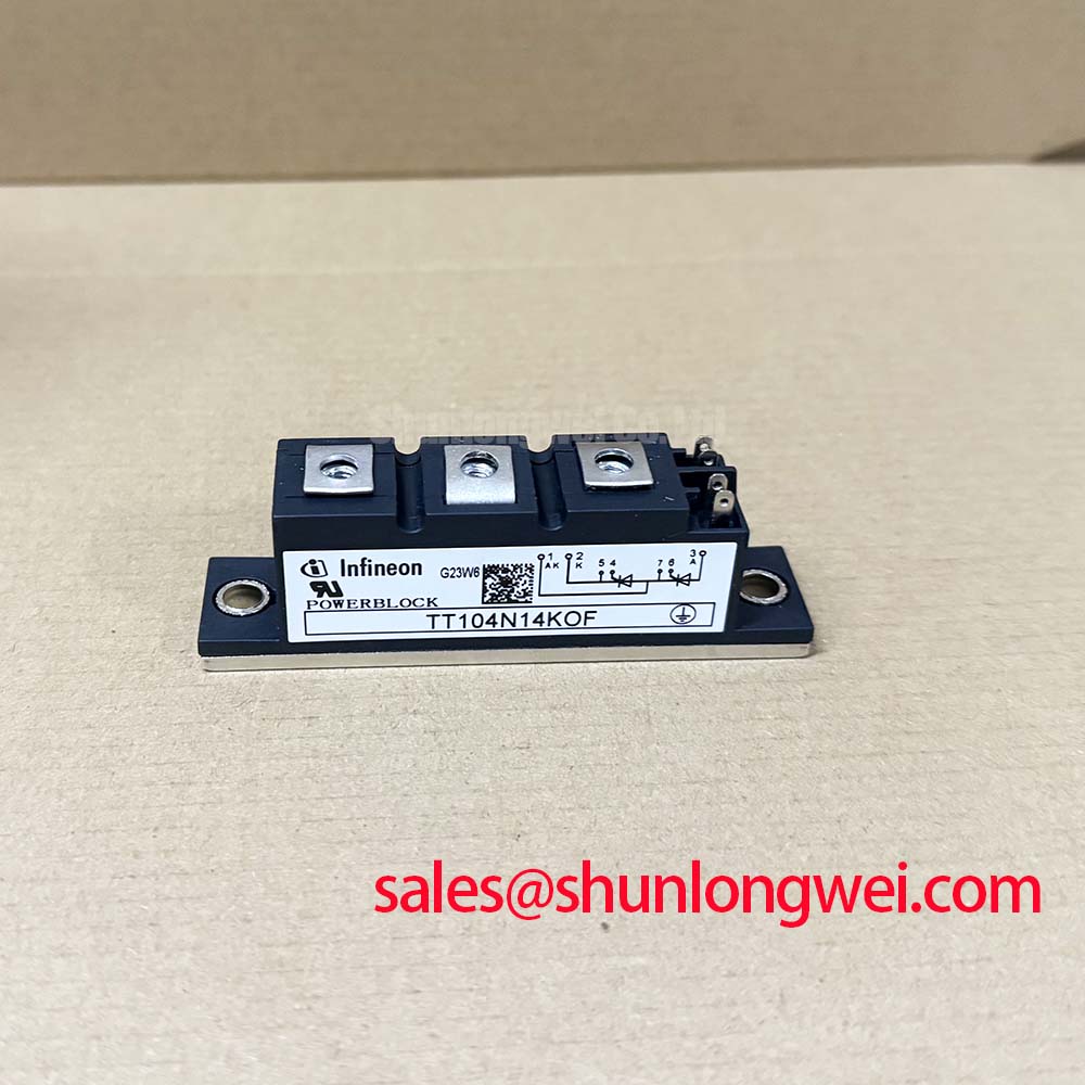
Verify the nameplate boundary and inspect the power terminals before installation: TT142N16KOF is an Infineon Dual Thyristor Module rated at 1600.0 V and 142.0 A, with a PowerBlock Module package. These are product specifications supplied for identification and initial system evaluation.
| Parameter | Specification |
|---|---|
| Manufacturer | Infineon |
| Model | TT142N16KOF |
| Product category | Dual Thyristor Module |
| Rated voltage | 1600.0 V |
| Rated current | 142.0 A |
| Package | PowerBlock Module |
For a replacement assessment, begin with the mechanical interface rather than energizing the circuit. Clean the heatsink contact area, check the baseplate for distortion or contamination, and confirm that the clamping arrangement follows the applicable Infineon mechanical documentation. The available product data identifies the PowerBlock Module package, but no verified thermal resistance value, mounting torque, fuse I²t table, or terminal torque is provided in the supplied specification set. Those values should be taken from the relevant manufacturer datasheet before release to production.
Thermal performance depends on uniform contact pressure, suitable thermal interface material, and a heatsink surface that is flat and clean. This is an Engineering Recommendation, not a model specific factory guarantee. Designers should inspect the spreading of the thermal compound without allowing excess material to reach insulated surfaces or terminals. The complete assembly should then be evaluated through measured case temperature and load current under the intended duty cycle.
In a grid tied static Var compensator or thyristor switched capacitor installation, the semiconductor fuse must be coordinated with the thyristor module’s verified surge and I²t limits. Do not substitute a fuse from a similar current class without checking the complete coordination table. Terminal lugs should be clean, correctly aligned, and tightened according to the original installation specification.
⚠️ Maintenance Note: Schedule periodic heatsink cleaning and contact temperature checks, especially where restricted airflow, dust, humidity, or condensation can change the thermal path.
Benchtop Waveform Tuning: Mitigating Stress via Harmonic Current Injection and Line Filter on TT142N16KOF
When evaluating the module on a bench, isolate the gate control circuit from the power section and confirm the intended firing sequence before applying high voltage. An SVC branch can show different current, power factor, and reactive power behavior as its firing angle changes; a thyristor switched capacitor branch has different switching constraints. A firing-angle sweep should therefore be treated as a system test, not as a standalone operating guarantee for this model.
Use an oscilloscope and properly rated differential probes to compare gate timing, anode to cathode voltage, and load current. Measured harmonic currents can expose interaction between the switching branch, line impedance, and filter network. The filter design remains system determined: engineers should verify resonance behavior, capacitor discharge conditions, source impedance, and peak voltage against the actual SVC topology.
The TT500N18KOF may be reviewed as a neutral reference for a related power conversion stage, but it should not be treated as a drop in replacement. Device ratings, gate requirements, package geometry, and protection coordination must be checked independently for every assembly.
For isolated control boards, designers should verify the optocoupler or digital isolator common mode transient immunity against the measured switching environment. Gate-command interlock behavior should be validated on the complete controller so that unintended firing commands are blocked before the power terminals are energized.
TT142N16KOF Operational Boundaries: Evaluating Dynamic Voltage Sharing and RC Damping in Limits
RC damping and surge absorption should be evaluated from recorded voltage waveforms rather than selected from a generic component list. A suitable network may include an RC snubber or MOV arrangement, but its values are determined by the branch inductance, switching current, capacitor bank, line impedance, and allowable repetitive stress. This is a Design Consideration. The supplied factory data does not establish a universal resistor, capacitor, MOV, or saturable reactor value for TT142N16KOF.
Place the measurement reference close to the module terminals and inspect turn on and turn off transitions under the intended firing sequence. In a series-connected arrangement, unequal voltage sharing can be associated with layout parasitics, gate timing, device mismatch, or an external commutation path; verify each possibility against a known good waveform rather than assigning a single cause. Any RC network must also be checked for resistor pulse capability, capacitor insulation performance, and heating during repetitive operation.
The engineering guide Wide Bandgap Revolution provides broader context on switching stress and power semiconductor design challenges. It is a technical reference, not a substitute for the thyristor module’s own electrical and mechanical documentation.
TT142N16KOF Thermal Electrical Optimization: Short Circuit Withstand Limits
Short circuit protection should be released only after the selected semiconductor fuse has been compared with the manufacturer’s verified thyristor withstand data. The clearing energy must remain compatible with the module’s permitted surge and I²t limits, while the fuse voltage rating, prospective fault current, coordination class, and installation inductance are reviewed together. Since those detailed values are not included in the supplied product parameters, no guaranteed fault clearing result can be assigned here.
During commissioning, record the fault protection response using equipment rated for the installation voltage. Inspect the module, busbars, fuse holder, and terminal hardware after a protection event; thermal discoloration or loosened connections may indicate that the complete assembly requires further investigation. Do not reuse a module after an overcurrent event without electrical testing and a documented engineering decision.
Infineon’s Automotive Qualified IGBTs page is a separate manufacturer resource and should not be interpreted as a qualification statement for this Dual Thyristor Module. For compatibility review, the TT570N16 can be examined as a related reference model, while voltage, current, package, gate control, cooling, and protection data must be confirmed independently before any replacement decision.