Content last revised on October 17, 2026
Preventing Spurious Faults: Cold-State Main Terminal Impedance Guidelines for MG50G2YL1A
- With the module disconnected and fully discharged, check the main terminals and any documented antiparallel-diode path using a digital multimeter in diode-check mode.
- Compare readings with a known-good unit of the same configuration; record meter polarity and lead placement rather than relying on an assumed pin order.
- Inspect the mounting surfaces and confirm that the heatsink, interface material, and terminal connections match the equipment’s service documentation.
- Keep the gate-drive circuit isolated from the module during incoming checks, and verify the driver’s isolation requirements from its own documentation.
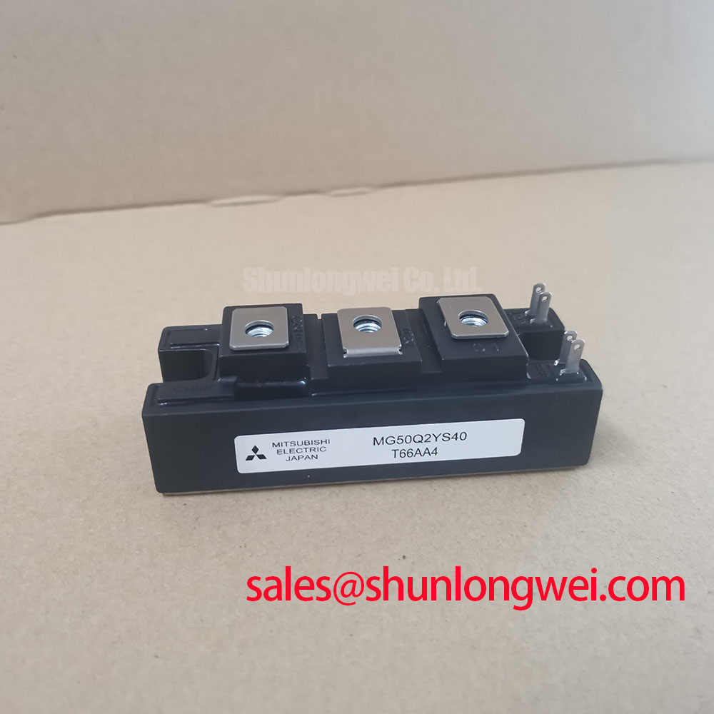
Toshiba MG50G2YL1A is listed with a 1200 V rated voltage, a 50 A rated current, and a Toshiba Module package. These are the stated product parameters; they do not by themselves define the allowable operating point in a particular inverter or motion-control assembly. For a repair assessment, first confirm the module marking and terminal identification against the equipment documentation, then compare static readings with a known-good device under the same cold, unpowered conditions.
💡 Bench Tip: Use ESD precautions and keep a consistent record of meter polarity, ambient condition, and probe placement so that a later comparison is meaningful.
Start the cold bench screen with the power stage isolated, the DC link discharged, and the module electrically separated from parallel circuit paths that could affect a meter reading. Confirm the instrument is functioning and note the test-lead polarity before probing. A diode-check reading is a comparative screening observation, not a substitute for a switching test or a definitive pass/fail limit unless the manufacturer’s test procedure specifies the conditions and threshold.
Identify the main terminals and gate terminals from the applicable Toshiba documentation before testing. Do not infer pin assignments from a similar-looking module or from a different MG-series part. With the meter in diode mode, test the documented main-terminal path in both polarities and record the displayed result. If the module documentation identifies an antiparallel diode path, check that path in its forward direction and reverse direction as well. A reading that differs materially from a known-good unit may point to a device issue, a wrong probe location, residual charge, or an external path still connected to the terminals; isolate those possibilities before drawing a conclusion.
Gate leakage screening also depends on the specified terminals and test conditions. Keep the gate and emitter connections clean and dry, avoid touching exposed contacts, and do not apply an improvised voltage source to the gate. Where the official test conditions are unavailable at the bench, record the static observation without converting it into an unsupported leakage limit. Before DC energization, check for unintended conductive paths between the gate-drive wiring and the power circuit, and inspect the assembled board for contamination or damaged insulation near switching nodes.
For a precision stepper or BLDC servo motion actuator, compatibility assessment should include the DC-link range, switching topology, control strategy, current waveform, and protection coordination of the complete drive. The listed 1200 V and 50 A values are product ratings, not a guarantee that a particular drive can operate at those values continuously. The system engineer should evaluate the expected load profile and switching conditions against the relevant module documentation and the drive’s thermal and electrical limits.
During field replacement planning, compare the complete configuration, pinout, package, and specified switching characteristics rather than selecting on current and voltage ratings alone. The MG30G2CL3 is another Toshiba module that may be included in a parts comparison, but its ratings and configuration must be assessed independently; the model name alone does not establish interchangeability with the MG50G2YL1A.
For layout review, keep the high-current commutation path compact and minimize parasitic loop inductance where practical. This is a Design Consideration: inductance in the switching loop can contribute to turn-off voltage overshoot, while the actual peak depends on the circuit, current transition, and interconnect. Engineers should verify switching waveforms and voltage margin in the assembled equipment under representative operating conditions. Where a measured peak is excessive, review busbar geometry, capacitor placement, connection integrity, and gate-drive behavior as parts of the same system investigation.
MG50G2YL1A Thermal-Electrical Optimization: Heatsink Surface Flatness and Thermal Grease Practical Tuning
Before mounting, inspect the module base and heatsink contact faces for debris, burrs, scoring, or visible distortion. Uneven contact can leave local gaps in the thermal interface and create a less consistent heat path. Clean both surfaces using a method compatible with the equipment materials, then apply the interface material evenly according to its supplier’s instructions. A thin, uniform layer is generally the objective; the correct material and application method depend on the module and heatsink specifications.
Use the module’s specified mounting hardware and tightening procedure. If the manufacturer provides a torque value and sequence, follow those instructions rather than substituting a general value. Tighten progressively in a diagonal pattern when the mounting arrangement calls for multiple fasteners, so the base is drawn toward the heatsink evenly. Do not use the fasteners to force a visibly warped surface flat. After installation, inspect the seating and confirm that the electrical connections and cooling assembly have not shifted.
Thermal assessment must reflect the actual duty cycle. In a servo actuator, repeated acceleration, deceleration, holding, and regenerative operation can produce a different thermal pattern from steady operation at a single load. Log heatsink or case temperature at defined operating states and compare the result with the limits and measurement locations specified for the module and system. A temperature reading without its sensor position, load condition, airflow state, and stabilization condition is difficult to interpret.
The switching protection path should be reviewed alongside thermal management. Desaturation protection commonly detects an abnormal rise in collector-emitter voltage during commanded conduction, but its threshold, blanking interval, and response timing belong to the driver and protection design. A stated detection interval such as less than 3 μs is not established here as an MG50G2YL1A specification and must not be treated as one. Designers should use the IGBT and gate-driver documentation to set a coordinated response that avoids nuisance trips while limiting fault energy.
Two-stage soft turn-off is one protection approach that can reduce abrupt current interruption during a fault: the driver first moderates the gate discharge and then completes turn-off according to its validated protection sequence. This is a system-level design consideration, not a guaranteed feature of the module. Validate the sequence with the selected driver and the actual power-stage layout, paying attention to the resulting collector-emitter voltage, current decay, and fault response. Do not assume that a protection setting tested on another module or inverter transfers unchanged.
Busbar arrangement also affects both electrical and thermal performance. A tightly coupled supply and return path can help limit loop inductance, while sound mechanical contact at terminals helps avoid localized heating. In bidirectional DC-DC applications, charge and discharge cycles can impose changing loss patterns; assess temperature across the operating modes used by the equipment rather than extrapolating from a single direction of power flow. This is an Engineering Recommendation for system evaluation, not a product-specific lifetime claim.
For broader context on cooling structures and thermal paths, see The Advanced Thermal Management Revolution. Thermal shock testing is a separate qualification topic; the referenced thermal shock overview describes the general phenomenon, not a qualification result for this Toshiba module.
Preventing Spurious Faults: Common-Mode Transient Immunity in Harsh Isolation Environments for MG50G2YL1A
Investigate false gate triggering by examining the complete isolation and return-current paths between the controller, gate driver, and power stage. Fast voltage transitions at a switching node can couple through parasitic capacitance and disturb the driver’s reference. The resulting behavior depends on the driver, PCB layout, isolation components, gate-loop impedance, and switching conditions; it is not a standalone immunity rating of the MG50G2YL1A.
Do not assign a reinforced-isolation withstand value or a common-mode transient immunity value to this module without an applicable manufacturer specification. Those figures are not among the stated product parameters. Select and verify the gate driver and isolation barrier using their own component documentation and the equipment’s insulation-coordination requirements. Keep the high-voltage switching region separated from low-voltage control routing in accordance with the applicable design rules and product safety requirements.
When a drive reports intermittent overcurrent or desaturation faults, capture the gate-emitter and collector-emitter waveforms at the module using suitable probes and safe measurement practice. Correlate the event with switching commands, DC-link behavior, motor-cable configuration, and fault logs. A short gate disturbance may be associated with common-mode coupling, but it can also arise from grounding, probe setup, driver supply behavior, or a real power-stage event. Compare against a known-good operating condition and change one test variable at a time.
Long motor cables can behave as transmission lines at fast switching edges, producing reflections that raise terminal voltage at the motor. The magnitude depends on cable length and construction, drive edge rate, motor impedance, and termination. Designers evaluating a precision motion actuator should consider the cable and motor as part of the drive system, then assess the waveform at the relevant points. Filtering or cable changes should be selected from system measurements and equipment requirements, not inferred from the module’s nominal voltage rating.
For incoming inspection, retain the module’s identification, the documented pin map, cold diode-check observations, and any later controlled test results together. That record supports comparison during repair without turning a single meter reading into a diagnosis. For the MG50G2YL1A, the confirmed stated ratings are 1200 V and 50 A in a Toshiba Module package; application limits and protection behavior remain dependent on the complete power-conversion design.