Content last revised on June 15, 2026
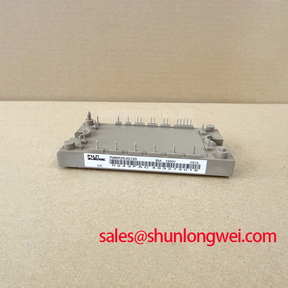
7MBI75SA-120B Fuji Electric 1200V 75A 7-Pack IGBT PIM Module
The 7MBI75SA-120B is a high-performance Power Integrated Module (PIM) from Fuji Electric, specifically designed for industrial power conversion applications. Integrating a three-phase inverter bridge and a brake chopper circuit into a single compact package, it offers a robust solution for engineers seeking to maximize power density while maintaining high thermal reliability. This module is built on Fuji Electric's advanced NPT (Non-Punch Through) technology, ensuring a balanced trade-off between switching speed and durability.
UVP: High-density 7-pack integration with optimized thermal resistance for space-constrained 1200V industrial drives.
- Top Specs: 1200V VCES | 75A Continuous Ic | 2.3V VCE(sat) (typical).
- Key Benefits: Reduced footprint in VFD designs; superior short-circuit ruggedness.
What distinguishes the 7MBI75SA-120B in drive design? It integrates a 3-phase inverter and brake into a single compact, thermally-efficient package, significantly reducing stray inductance and assembly complexity. For industrial motor drives requiring 1200V isolation and 75A continuous current in space-constrained enclosures, this module serves as a reliable power backbone.
Key Parameter Overview
Decoding the Specs for Enhanced Thermal Reliability
The following technical data is derived from the official Fuji Electric specifications. To understand the operational limits of the 7MBI75SA-120B, engineers must evaluate the relationship between collector current and junction temperature.
| Category | Parameter | Value (at 25°C) |
|---|---|---|
| Maximum Ratings | Collector-Emitter Voltage (Vces) | 1200V |
| DC Collector Current (Ic) | 75A | |
| Electrical Characteristics | Collector-Emitter Saturation Voltage (Vce_sat) | 2.3V (typ) / 2.8V (max) |
| Turn-on Time (ton) | 0.65µs (typ) | |
| Short Circuit Withstand Time (tsc) | 10µs (min) | |
| Thermal Characteristics | Thermal Resistance IGBT (Rth_jc) | 0.24 °C/W (max) |
| Operating Junction Temperature (Tj) | -40 to +150 °C |
Application Scenarios & Value
Achieving System-Level Benefits in Industrial Power Conversion
The 7MBI75SA-120B is strategically engineered for Variable Frequency Drive (VFD) and Servo Drive systems where reliability and compact mechanical layout are non-negotiable. Engineers often face the challenge of managing heat in high-density control cabinets. The low Thermal Resistance of 0.24 °C/W allows for more efficient heat transfer to the cooling system, enabling higher current densities without exceeding safe junction temperatures.
In a typical CNC machine or industrial robotic arm application, the integrated brake chopper of the 7MBI75SA-120B provides a critical safety and performance function by dissipating regenerative energy during rapid deceleration. This integration simplifies the Gate Drive layout and reduces the overall part count on the PCB. Furthermore, the 10µs Short-Circuit Withstand Time provides a vital safety margin, allowing the system controller to detect a fault and shut down before catastrophic failure occurs, ensuring compliance with IEC 61800-3 standards.
For systems requiring higher current handling within the same series, the 1MBI300SA-120B offers a higher collector current rating of 300A, while the 2MBI200SB120-50 provides a different topology for modular designs.
Technical & Design Deep Dive
Thermal Management and Package Integration Strategies
The internal architecture of the 7MBI75SA-120B utilizes a sophisticated DCB (Direct Copper Bonding) substrate, which serves as the primary thermal path. To visualize the Thermal Resistance (Rth), consider it like a "drainpipe" for heat: a wider, smoother pipe (lower Rth) allows a higher volume of heat to escape from the silicon chip to the heat sink. At 0.24 °C/W, this module ensures that even under heavy inductive loads, the silicon remains within its safe operating area (SOA).
Another critical design parameter is the Collector-Emitter Saturation Voltage (Vce_sat). One can think of Vce_sat as a "toll fee" paid in voltage every time current passes through the IGBT. A lower toll (2.3V) means less energy is wasted as heat during the conduction phase, directly increasing the overall efficiency of the inverter stage. By minimizing these conduction losses, the 7MBI75SA-120B allows for higher switching frequencies in PWM control schemes, which reduces torque ripple in AC motors and improves dynamic response.
When designing the power stage, minimizing stray inductance is paramount to prevent voltage spikes (V = L * di/dt) during fast switching. The PIM package layout of the 7MBI75SA-120B naturally optimizes the internal busbar routing, offering a much lower parasitic inductance compared to discrete IGBT and Diode solutions. This physical path to high power density is a key advantage for modern industrial display control systems and heavy machinery drives.
FAQ
How does the 10µs short-circuit withstand time impact the choice of Gate Drive controller?
The 10µs minimum withstand time allows engineers to use standard desaturation detection circuits in the Gate Drive. This timeframe is sufficient for the driver to sense the rising Vce during a fault and execute a "soft turn-off," preventing the high di/dt that could lead to overvoltage failure.
What are the implications of the 2.3V Vce(sat) for overall system efficiency?
A 2.3V typical Vce(sat) at 75A implies that conduction losses are kept low. In a 24/7 industrial VFD application, this translates to significantly lower cumulative energy waste and reduced cooling requirements, potentially allowing for a smaller, more cost-effective heat sink design.
As a specialized distributor, we provide comprehensive technical data to empower your engineering decisions. For detailed procurement specifications or to verify technical compatibility with your Power Semiconductor architecture, contact our technical sales team for expert support.