
Content last revised on June 30, 2026
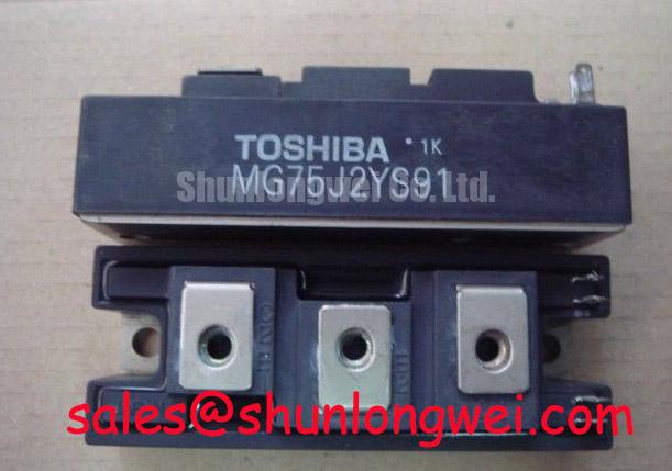
MG75J2YS91 IGBT Module: 600V, 75A Half-Bridge for Industrial Power Conversion
Engineering Product Analysis
A Distributor's Technical Perspective for OEM Engineers and Procurement Specialists
The MG75J2YS91 is a workhorse 600V dual IGBT module engineered for predictable performance in demanding power conversion systems. This device provides a streamlined solution for managing the core switching function in three-phase inverters by integrating two IGBTs in a half-bridge configuration. Its specifications are tailored for applications where robust power handling and straightforward thermal design are paramount. Best suited for cost-effective industrial motor drives up to 25kW, where predictable thermal performance and a simplified half-bridge topology are key design priorities.
Key Parameter Overview
Decoding the Specs for Thermal and Electrical Design
The performance of the MG75J2YS91 is defined by its core electrical and thermal characteristics. These parameters are critical inputs for calculating system efficiency, designing effective cooling solutions, and ensuring the device operates within its specified safe limits. The following table highlights the specifications that directly influence its application in industrial power systems.
| Parameter | Symbol | Value | Conditions |
|---|---|---|---|
| Collector-Emitter Voltage | Vces | 600V | VGE = 0V |
| Collector Current (DC) | Ic | 75A | Tc = 80°C |
| Collector Current (Peak) | Icp | 150A | Pulse Width ≤ 1ms |
| Collector-Emitter Saturation Voltage | Vce(sat) | 2.7V (Max) | Ic = 75A, Vge = 15V |
| Forward Voltage (Diode) | Vf | 2.5V (Max) | If = 75A |
| Thermal Resistance (Junction-to-Case) | Rth(j-c) | 0.33 °C/W (per IGBT) | - |
| Isolation Voltage | Visol | 2500V | AC, 1 minute |
Application Scenarios & Value
Achieving System-Level Benefits in AC Motor Control
The MG75J2YS91 is fundamentally designed for the power output stage of Variable Frequency Drives (VFDs) and other industrial motor controllers. Its 600V rating makes it a solid choice for systems operating on 200/230V AC lines, providing substantial voltage headroom for handling transient overvoltages common in industrial environments.
Consider the engineering challenge of designing a compact 15kW VFD for a conveyor belt system. The primary goal is to manage the heat generated by the power electronics within a sealed enclosure. The MG75J2YS91's specified maximum Vce(sat) of 2.7V is a critical parameter for this task. It allows engineers to precisely calculate the worst-case conduction losses, which is the dominant loss factor at lower operating frequencies typical of such applications. This calculation directly informs the required heatsink performance, enabling a thermal design that is neither over-engineered and costly nor undersized and unreliable. The integrated half-bridge configuration further aids in creating a compact power stage by simplifying the PCB layout and minimizing stray inductance between switches. For systems demanding higher power output, the related MG150Q2YS50 offers double the current handling capability within a similar module footprint.
Technical Deep Dive
A Closer Look at Power Loss and Thermal Management
An effective power design hinges on a thorough understanding of loss mechanisms. For an IGBT module like the MG75J2YS91, total power dissipation is a sum of conduction losses and switching losses. The module's Vce(sat) is the key determinant of conduction loss. Think of VCE(sat) as the 'friction' of the electronic switch. Just as mechanical friction generates heat, a higher VCE(sat) results in more thermal energy being produced as current passes through the device. The 2.7V maximum rating provides a firm ceiling for this loss component.
Switching losses (Eon and Eoff), while not the primary focus for this class of device, become increasingly significant as the PWM frequency rises. The datasheet provides typical switching time values that allow for an estimation of these losses. The crucial next step is translating total power loss into a temperature rise. This is where the Rth(j-c) value of 0.33 °C/W becomes vital. This parameter quantifies how effectively heat can travel from the silicon chip to the module's baseplate. A lower Rth(j-c) is always better, as it means the junction will run cooler for a given amount of power dissipation. A comprehensive mastery of thermal management is essential for leveraging the full capability of the MG75J2YS91 without compromising its operational lifespan.
Frequently Asked Questions (FAQ)
How does the half-bridge (2-in-1) configuration of the MG75J2YS91 benefit my design?
The integrated half-bridge topology significantly simplifies the design of a three-phase inverter. Instead of mounting and connecting two separate discrete IGBTs per phase, you use a single module. This reduces assembly complexity, minimizes PCB trace lengths, and lowers stray inductance, which can help mitigate voltage overshoot during high-speed switching events.
What is the primary implication of the 2.7V maximum Vce(sat) for my thermal design?
The 2.7V Vce(sat) at the nominal 75A current rating allows you to calculate the maximum conduction power loss per switch (P_cond = 2.7V * 75A = 202.5W). This worst-case value is a critical input for selecting a heatsink and/or fan combination that can maintain the IGBT junction temperature below its maximum limit (typically 150°C), ensuring long-term reliability.
Is the integrated freewheeling diode (FWD) sufficient for hard-switching motor drive applications?
Yes, this module includes an FWD that is co-packaged and optimized for handling the inductive turn-off events inherent in motor control. The diode is rated to handle the same nominal current as the IGBT and exhibits fast reverse recovery characteristics (trr), which is essential for minimizing losses and protecting the IGBT during commutation in a PWM inverter bridge.
Strategic Outlook for Industrial Power Design
While the pace of power semiconductor technology is rapid, modules like the MG75J2YS91 retain their place in the market by offering a proven, reliable, and cost-effective foundation for a vast range of industrial applications. For design teams focused on optimizing established platforms or developing new systems where time-to-market and predictable performance are prioritized, this module provides a robust and well-characterized building block. The key to successful implementation lies not in pushing the boundaries of switching frequency, but in leveraging its solid thermal and electrical characteristics to build efficient and highly reliable power conversion systems that stand the test of time.