Content last revised on September 21, 2026
MIG75J101H Thermal-Electrical Evaluation for High-Altitude Operation and SEB Risk
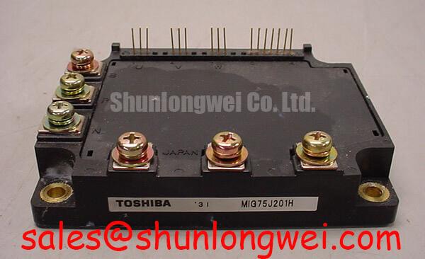
Before fitting a replacement module, isolate the converter, confirm that the DC link has discharged according to the equipment procedure, inspect the module case and terminals for heat discoloration or mechanical stress, and verify the nameplate electrical boundary. The MIG75J101H is a Toshiba IGBT module rated at 600 V and 75 A, supplied in a module package. These are Official Datasheet Specifications and should be matched against the original converter bill of materials and electrical design documentation.
For commercial string inverter and micro grid energy storage equipment, the module must be assessed as part of the complete switching assembly rather than from its current label alone. DC bus operating voltage, switching waveform, heatsink condition, gate drive behavior, load profile, and enclosure temperature all affect the electrical and thermal stress seen in service. The stated 600 V rating is an official blocking voltage boundary, not a statement that every 600 V bus arrangement is automatically suitable. System engineers should validate switching peaks and repetitive operating conditions using the original equipment design limits.
High altitude operation deserves separate attention because environmental conditions can alter system level insulation coordination, cooling performance, and surge behavior. No device specific FIT rate, cosmic ray susceptibility figure, or single event burnout rate is stated here because such figures require a manufacturer specification or a qualified published source. As a Design Consideration, equipment operating at elevation should be reviewed against the converter manufacturer’s altitude requirements, including DC bus derating policy, enclosure clearances, and cooling capacity.
Thermal evaluation should follow the actual duty cycle. A transient thermal impedance network is useful because short load events do not heat the silicon junction and heatsink at the same rate as continuous output. Maintenance teams can compare module case temperature, heatsink temperature, airflow condition, and load behavior over a repeatable operating cycle. A rising temperature trend can indicate restricted airflow, aged interface material, uneven mounting pressure, or a changed operating profile, but each possibility should be checked with measured evidence.
Maintenance Note: Periodically monitor terminal and heatsink contact temperature while the equipment is operating under a controlled load, then inspect the cooling path for dust accumulation, fan degradation, moisture ingress, and condensation risk.
For broader application context, the Industrial Applications guide provides system level discussion of power semiconductor use across renewable energy and industrial conversion equipment.
MIG75J101H Operational Boundaries: Evaluating Optocoupler vs Digital Coreless Transformer Limits
The MIG75J101H module does not define the isolation capability of a gate driver. Isolation performance belongs to the selected driver, its PCB layout, its power supplies, and the finished converter assembly. When integrating this 600 V, 75 A Toshiba module, designers should verify the required galvanic isolation level, creepage and clearance distances, common mode transient behavior, and protection response against the original drive board documentation.
Optocoupler based drivers and digitally isolated drivers can both be found in industrial power equipment, but they must not be treated as interchangeable on the basis of package appearance or nominal isolation wording. Propagation behavior, supply arrangement, fault response, output drive capability, and noise immunity need evaluation within the actual switching environment. A drive circuit that behaves correctly at low voltage bench conditions can show unwanted gate activity when exposed to converter common mode transients.
As a Design Consideration, keep the gate command and return path physically controlled to reduce susceptibility to switching noise. The relevant condition is suppression of unwanted gate movement during fast collector voltage transitions, and the final layout should be verified by probing the installed converter under controlled switching tests. Dead time and gate resistor selection are system determined values; they should be retained from the qualified original design or established through measured validation of crossover current, switching loss, and voltage overshoot.
The freewheeling path also deserves attention during repair analysis. Reverse recovery behavior, loop inductance, snubber condition, and bus capacitor connection all contribute to switching stress and radiated noise. A noisy waveform does not identify a single failed part. It may indicate a changed gate drive path, degraded snubber component, poor DC link connection, or a measurement setup that is picking up common mode interference. Compare measurements with a known good phase or documented reference waveform where available.
Current feedback is another part of the protection chain that should be checked before declaring the power module responsible for a trip event. The TI current sense amplifier and shunt monitor overview is useful background when reviewing how current measurement circuits influence overcurrent detection and controller decisions. The sensor type, scaling, filtering, and controller thresholds remain properties of the equipment design.
Transient Dynamics & Electrical Design: Thermal Interface Material Thickness Uniformity on MIG75J101H
Remove aged thermal interface material completely from both the MIG75J101H mounting face and the heatsink before evaluating a replacement installation. Clean surfaces make it possible to identify scoring, corrosion products, embedded debris, or localized discoloration that can disturb thermal contact. Do not infer internal module damage from one visible mark alone; inspect the mating surface, mounting hardware, airflow route, and measured temperatures together.
A thin, uniform thermal interface layer is a Design Consideration for reducing thermal resistance between the module and its heatsink. The correct material, application method, thickness control, and tightening sequence must be confirmed from the equipment service documentation and module mechanical drawing. Excess material can increase the thermal path, while voids or debris can create uneven contact areas. Baseplate and heatsink flatness should also be assessed when recurring thermal alarms occur after replacement.
Sequential tightening is important because it helps distribute mounting pressure across the module footprint. The applicable torque and hardware requirements are not asserted here as Toshiba specifications because they have not been provided in the official parameter set. Use the module drawing and the equipment manufacturer’s service instructions to determine the correct fastener details. After initial thermal cycling, maintenance personnel can recheck mounting integrity according to the approved service schedule, especially where vibration and repeated temperature changes are present.
In bidirectional DC DC stages used with battery energy storage, charging and discharging can impose repeated thermal cycles on the power assembly. The practical response is not to assume a service life from generic cycle counts. Instead, record operating temperature trends, cooling system condition, switching frequency set by the controller, and load history. A stable, repeatable baseline makes it easier to identify a developing change before a protection event becomes a shutdown.
When a cross reference is being evaluated, package fit, voltage class, current rating, terminal arrangement, drive requirements, thermal interface requirements, and protection compatibility must all be verified. The MG75H6EL1 can be reviewed as a separate product option, but it should not be assumed to be a direct replacement for the MIG75J101H without engineering comparison against the original assembly.
Preventing Spurious Faults: Desaturation Detection Guidelines for MIG75J101H
Desaturation protection is implemented by the gate driver and surrounding control circuit, not by the external nameplate rating of the IGBT module. For a MIG75J101H installation, technicians should first confirm that the driver receives its intended supply conditions, that the desaturation sensing path is intact, and that the controller is not responding to an unrelated current, temperature, interlock, or DC bus fault. A repeated fault signal may originate in several locations, so the diagnostic path should remain evidence based.
In many power converter architectures, the driver monitors collector emitter behavior after a controlled blanking interval and initiates a protected turn off response when the monitored condition exceeds the system threshold. That threshold, blanking interval, short circuit operating area assessment, and soft turn off profile are system specific. They should be taken from the qualified drive design and verified with suitable isolated measurement equipment. Replacing these values with generic settings can increase switching stress or produce nuisance trips.
A controlled soft turn off sequence is commonly considered where inductive current must be interrupted during a protection action. Its purpose is to manage the tradeoff between fault clearing speed and transient overvoltage. As an Engineering Recommendation, evaluate the complete current path, DC link capacitor placement, gate driver response, and measured collector voltage during controlled protection testing. The final acceptance criteria should be defined by the equipment engineering team and the applicable original documentation.
For field fault isolation, compare the affected phase with an equivalent known good phase where the topology permits it. Inspect driver connectors, gate return continuity, current sensor connections, busbar tightness, heatsink airflow, and control board alarm history. Check waveform measurements against the known good signal path using correctly rated differential or isolated instruments. This approach helps separate gate drive noise, sensor errors, thermal conditions, and power stage abnormalities without assigning a fault to the module prematurely.
The MIG75J101H should therefore be assessed within its documented 600 V and 75 A official rating boundaries, with the converter’s existing protection architecture, thermal assembly, and maintenance records treated as essential parts of the integration decision.