

Content last revised on October 13, 2026
Dynamic Contrast Ratio Stabilization and Liquid Crystal Birefringence Temperature Tracking
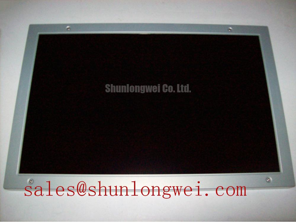
Grayscale instability in a diagnostic display should first be separated into optical behavior, timing behavior, and backlight behavior. A change in viewing angle, ambient illumination, or panel temperature can alter perceived contrast even when the video source remains unchanged. During evaluation of the NL192120AC25-02, record the image condition at the same viewing position and with the same host display settings. This helps distinguish a true panel response issue from a change caused by surrounding light or image-processing configuration.
TN, IPS, and MVA technologies do not produce identical viewing-cone behavior, grayscale transitions, or off-axis contrast. The specific panel technology for this model should therefore be confirmed from the equipment documentation before applying a compensation table or changing the T-CON configuration. A grayscale ramp is more useful than a single test image because it exposes crushed levels, inversion-like transitions, gamma discontinuities, and channel imbalance across the visible range.
Temperature tracking should focus on repeatable observations rather than assumed liquid-crystal constants. Allow the display to reach the normal enclosure condition, then compare dark-level stability, mid-gray uniformity, and highlight detail. If a constant-current backlight driver is used in the equipment, examine brightness stability and thermal distribution at the driver output. A claimed 50,000-hour or 50 percent brightness point must come from the applicable backlight specification or reliability report; it should not be assigned to this NEC panel without a source.
Anti-glare treatment also affects field judgment. Surface reflections from surgical lighting, ultrasound room luminaires, or protective windows can reduce perceived contrast without indicating a failure of the active matrix. Use the same cover glass, bezel, and ambient lighting arrangement during comparison. The industrial display reference provides useful context for evaluating display optics, but it does not establish undocumented specifications for this model.
Eye-Diagram Voltage Margin and Differential Noise-Floor Verification in High-Vibration Bays
Pixel jitter and horizontal noise bands near variable-frequency motor drives require an examination of the complete signal route, including the host graphics output, cable shield termination, connector mechanics, and panel-side receiver. Do not attribute the symptom to the LCD cell alone. If the interface uses differential signaling, capture the differential video waveform at the receiving end when practical, and compare the eye opening and common-mode behavior with the same cable connected to a known-good display path.
A shielded FFC or LVDS cable should be routed away from high-current motor conductors and switching nodes. Shield continuity must be checked across the actual installed assembly, including any intermediate connector or chassis transition. Grounding decisions belong to the system EMC design because an incorrect shield return can convert common-mode energy into visible periodic bands. Ferrite components may be evaluated as part of that system design, but they are not identified as accessories supplied with the NL192120AC25-02.
High vibration adds a mechanical failure mode to the electrical investigation. Inspect the connector latch, cable bend radius, clamp points, and panel frame loading while the image is monitored. A display that changes when the bezel or cable is gently moved may have an interface or mounting issue, but the observation should be confirmed with continuity and signal measurements rather than treated as a single definitive diagnosis.
For a separate reference within the same sourcing workflow, engineers can review NL8048AC19-13. It should be treated as a separate display product for comparison, not as an automatic substitute. Resolution, active area, connector arrangement, timing, mounting geometry, and optical characteristics must align before any replacement decision.
| Evaluation item | NL192120AC25-02 | NL8048AC19-13 reference |
|---|---|---|
| Manufacturer | NEC | Separate product record |
| Product category | LCD Display | Confirm from applicable documentation |
| Display construction | TFT-LCD Active Matrix Color Display Module | Confirm from applicable documentation |
| Replacement status | Requires system-level compatibility review | Requires system-level compatibility review |
Diffuser Film and Prism Sheet Thermal Buckling Prevention under Continuous Full-Duty Operation
Thermal non-uniformity becomes visible when a narrow display assembly is constrained unevenly by the bezel or when heat is concentrated near the backlight and controller areas. Mechanical pressure should be checked across the frame, especially at corners and along narrow edges. A heat-spreader rail can be considered when enclosure measurements show a localized hot area, but its material, contact pressure, insulation, and grounding must be selected by the system designer.
Do not assume that diffuser films, prism sheets, or light-guide materials are present in a particular construction unless the panel documentation confirms them. Optical layers can respond differently to temperature and mechanical loading, so the practical check is to compare luminance uniformity, edge shading, and any developing bright or dark bands before and after the display reaches its normal operating condition.
Backlight service life should be assessed from the actual backlight assembly and drive current conditions. L70 or B50 terminology is meaningful only when the corresponding test definition, temperature, current profile, and failure criterion are known. The NEC product identity supplied for this page does not provide those lifetime values. For coordinated display sourcing, LQ181E1LW31 may be reviewed as a separate display-related reference, not as a confirmed companion driver for this panel.
T-CON behavior deserves equal attention. Inspect the gray-scale response across the full image area, then compare static patterns with moving diagnostic images. Gamma correction may be implemented in the panel electronics, the host controller, or both. Changing a gamma table without recording the original values can conceal the actual fault and create a new calibration mismatch. When the display is used in a high-precision ultrasound or surgical imaging terminal, the integrator should validate grayscale reproduction against the system’s approved image-quality procedure.
💡 Pro Tip: If the interface uses differential signaling, keep the differential clock and data paths physically consistent through the connector and panel interface, then verify image stability at the actual enclosure temperature rather than only on an open bench.
Interface Verification, Pixel Clock and Skew Compensation
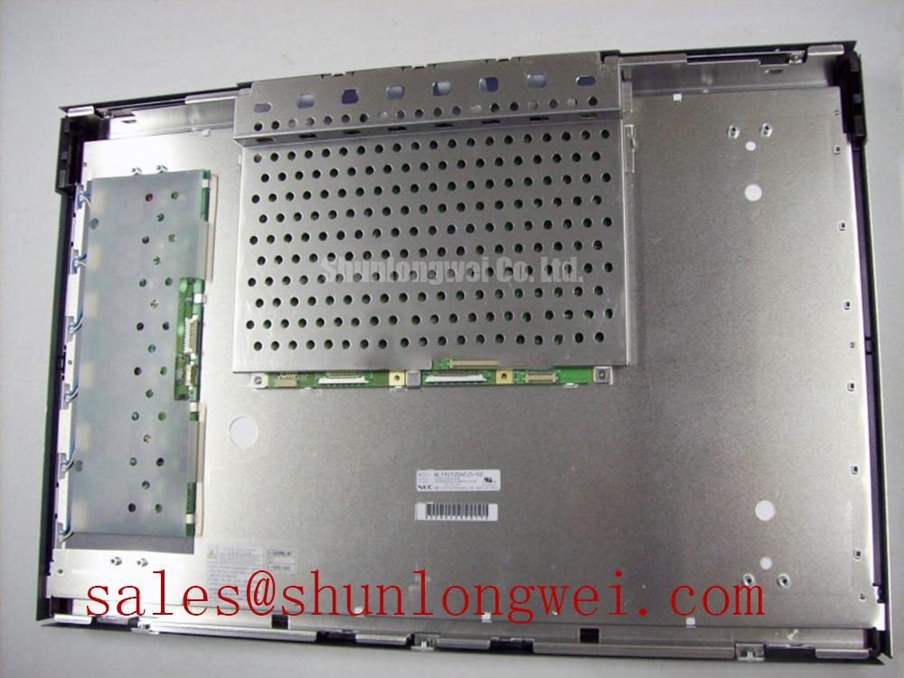
Connector count and signal format must be confirmed from the original panel documentation before a cable is fabricated. The model record identifies the unit as a TFT-LCD active matrix module, but it does not establish whether the installed system uses a particular 20-pin or 30-pin assignment, LVDS lane arrangement, TTL interface, logic supply, or backlight control method. The system integrator should verify the required supply voltage, pin definition, polarity, and power sequence from the original display documentation.
During replacement evaluation, map the host output to the panel input by signal name rather than by physical pin position alone. Check the applicable pixel clock polarity, data ordering, lane mapping, and any JEIDA or VESA format selection. A mapping error can produce split images, incorrect colors, repeated columns, or unstable synchronization even when the connector fits mechanically.
For high-EMI industrial equipment using a differential interface, differential routing should preserve a controlled characteristic impedance consistent with the transmitter, receiver, and cable design. The commonly used 100-ohm LVDS target is a system design reference, not an official electrical specification for this NEC model. Pair symmetry, return-path continuity, connector transitions, and skew should be evaluated together. The acceptable timing margin is determined by the actual transmitter and receiver data sheets, operating temperature, cable construction, and measured eye diagram.
Power sequencing is equally important. Observe the panel supply ramp, enable signals, reset behavior, and video activation order with an oscilloscope during cold start and warm restart. Avoid repeated connector insertion while energized; it can disturb the interface and expose the panel to uncontrolled transients. The correct startup interval must satisfy the applicable panel requirements as well as the system design.
For broader design context, the industrial TFT LCD technology guide discusses interface selection, optical behavior, and common integration assumptions. Engineers evaluating the NEC module for a medical imaging display should also review the manufacturer’s public NEC website while keeping final compatibility decisions tied to the installed equipment records.
Before approving the NL192120AC25-02 for a high-precision surgical navigation or ultrasound diagnostic display, confirm the active area, resolution, interface pinout, timing format, power requirements, backlight architecture, mounting geometry, and optical stack against the original panel documentation. These checks protect the image path, mechanical fit, and service repeatability without assigning unsupported parameters to the NEC product.