


Content last revised on September 14, 2026
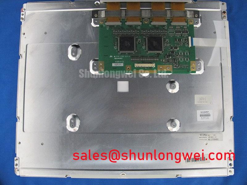
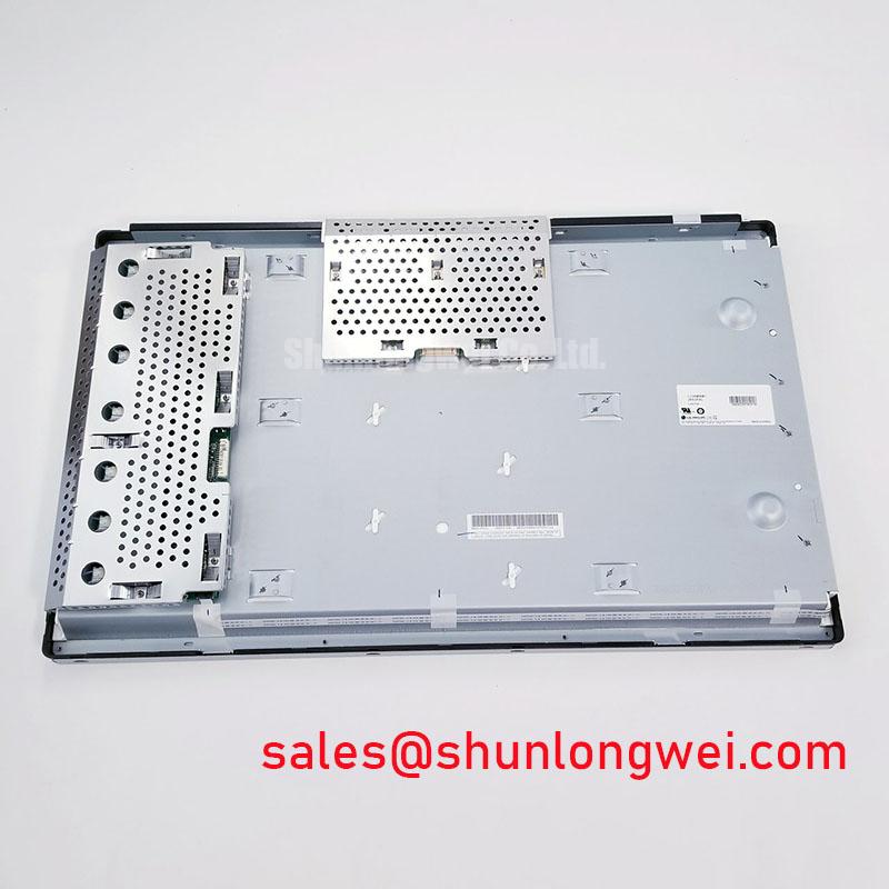
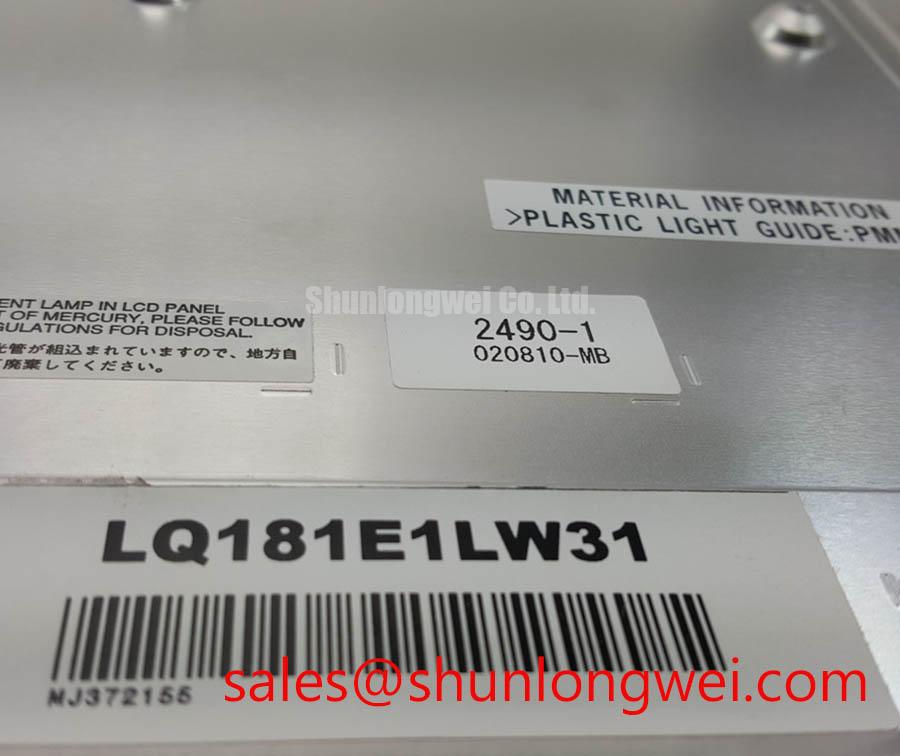
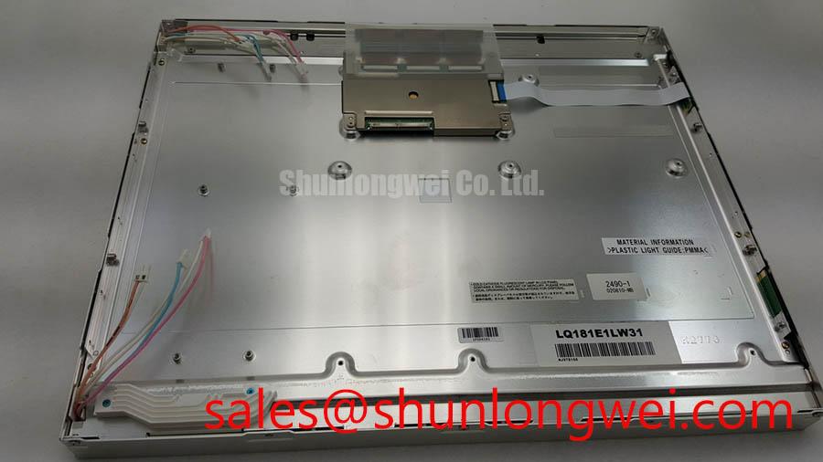
LQ181E1LW31 Inspection and Identification
Begin inspection of the LQ181E1LW31 with the equipment fully isolated, then compare the module label, display outline, connector orientation, and mounting points against the original machine documentation before disconnecting the signal cable. This Sharp unit is identified as an Industrial Grade LCD/HMI Panel in a TFT-LCD Display Module enclosure. The available official product identification does not confirm its native resolution, input voltage, timing, backlight type, optical mode, connector pinout, or operating-temperature rating; the system integrator should verify these items from the original panel documentation and host-controller records before replacement or redesign work.
| Model | LQ181E1LW31 |
| Manufacturer | Sharp |
| Product Category | Industrial Grade LCD/HMI Panel |
| Module Format | TFT-LCD Display Module |
| Specification Status | Limited Official Product Identification Available |
Micro Twist Mechanical Stress Screening Before Attributing Lines to Driver Bumps
A field evaluation should begin with a stable bench fixture that supports the display perimeter without loading the active area. Do not use the rear housing as a lever point while connecting the original cable assembly. Check for frame distortion, uneven fastening pressure, damaged connector latches, localized edge marks, or evidence that the host bezel has imposed stress on the panel. These observations do not establish an internal failure mechanism by themselves, but they help separate external mechanical concerns from signal-path concerns.
Run a controlled primary-colour pattern sequence using red, green, blue, white, black, and neutral-grey images from a known-good controller path. Observe whether a line, block, or intermittent image region changes with content, connector movement, chassis movement, or temperature stabilization. A flashlight held at an oblique angle can help distinguish an illuminated but image-defective area from a region where backlight output appears absent. This is a diagnostic aid rather than a conclusive fault classification, because optical layers, source data, power sequencing, and panel electronics can produce visually similar symptoms.
Design Consideration: if the host documentation identifies a differential display interface, the cable and PCB route should preserve pair symmetry, controlled impedance appropriate to the transmitter and receiver standard, and matched propagation delay. The applicable impedance target and skew budget must come from the confirmed interface specification and the host-board stack-up, rather than being assumed from the LQ181E1LW31 model name. If the equipment uses a TTL interface instead, LVDS routing rules should not be applied by default.
⚡ Safety Interlock Note: Disconnect display power and allow the host system to discharge before reseating a panel cable, because live insertion can create transient conditions that complicate fault isolation.
For a potential alternate-module assessment, engineers can compare the mechanical drawing, connector location, confirmed interface format, timing compatibility, and optical requirements of the LM190E08-TLG6 with the original equipment documentation. Similar product positioning or screen class does not establish electrical or mechanical interchangeability.
Assessing Frame Lag and Image Smearing After Cold Exposure
If a machine has been stored in a cold outdoor area, allow the display and host controller to stabilize before diagnosing image lag, ghosting, or incomplete transitions. Liquid-crystal response can change with temperature, while the controller, cable, supply rail, and backlight assembly can also contribute to a poor visual result. A repeatable test should compare the same moving image pattern before and after environmental stabilization, using the original host electronics wherever possible.
The official identification available for the LQ181E1LW31 does not state a low-temperature limit, high-temperature limit, grey-to-grey response value, perimeter-seal construction, or thermal-cycle qualification. It would therefore be inaccurate to assign a specific outdoor temperature range or seal durability claim to this module. Design Consideration: equipment designers should assess the complete display stack, including enclosure sealing, bezel loading, ventilation, cable flexibility, and the machine’s actual thermal exposure, against the validated requirements of the finished equipment.
Backlight brightness decline should also be treated as a system-level observation unless the original Sharp documentation defines an applicable luminance-maintenance condition. A dim image can arise from the panel backlight, driver circuitry, dimming control, supply stability, or an optical path obstruction. Measure the relevant power rails and control signals against the known-good equipment reference before deciding that the display module is the source of the issue.
When reviewing the display power path, a related display solution such as LMS700KF01-001 can be examined as a separate product reference. Its presence in a sourcing review does not indicate that it is electrically compatible with the LQ181E1LW31 or that it can replace any original backlight-control function.
Power sequencing deserves particular attention during repair. The original panel documentation should define the order in which logic supply, display data, enable controls, and illumination controls are applied and removed. Where a white screen or residual image appears during start-up or shutdown, capture the relevant rails and control lines with appropriate instrumentation and compare them with the host design intent. Avoid changing supply order or adding delay components without confirming the panel interface requirements.
Viewing Angle and Backlight Dimming Checks for Multi Angle Consoles
Evaluate the LQ181E1LW31 from the intended operator positions using a static grayscale image, text screen, colour bars, and a moving interface screen. Record contrast loss, colour shift, brightness non-uniformity, or inversion-like behaviour by viewing direction. The official product information provided does not identify this Sharp panel as TN, IPS, MVA, Super-IPS, or any other optical technology, and it does not state a symmetric viewing-angle specification. Such attributes must be verified from the original Sharp panel documentation rather than inferred from application requirements.
Anti-glare performance should be reviewed as an enclosure-level characteristic when the display is used behind a protective window or touch overlay. Surface reflections can be affected by the panel finish, cover lens, adhesive selection, viewing angle, cabin lighting, and contamination on the outer surface. Optical bonding may be evaluated by the finished-equipment designer where moisture, dust, or internal reflections are a concern, but bonding pressure, adhesive chemistry, and rework method must be validated against the panel’s approved mechanical limits.
Design Consideration: dimming compatibility depends on the confirmed backlight architecture and the host driver’s control method. Do not assume a PWM frequency, duty-cycle characteristic, enable polarity, or analogue dimming range for this specific module without the original documentation. If flicker is visible in text or camera recordings, inspect the driver output, dimming command waveform, and grounding relationship while comparing the result with a known-good display assembly.
💡 Pro Tip: Keep confirmed differential signal pairs physically consistent through the cable transition and connector area to reduce clock-related pixel instability in electrically noisy equipment bays.
Industrial HMI interfaces with long static screens should be reviewed for residual-image behaviour through the panel manufacturer’s defined operating guidance, if available. Interface designers can reduce persistent static-image exposure through controlled screen-content practices, but no retention or burn-in performance claim should be assigned to the LQ181E1LW31 without a model-specific specification.
Eye Diagram and Differential Noise Floor Verification in High Vibration Bays
Horizontal bands, intermittent pixel jitter, or image loss near motor drives should be evaluated as an installation and signal-integrity issue before attributing the condition to the display module. Inspect cable restraint, connector retention, chassis bonding, shield termination, routing near switching conductors, and the host controller output. Vibration can alter cable contact pressure or expose an already marginal grounding path, while conducted noise can affect the display supply and the transmitter independently.
Where the confirmed interface is LVDS, use an oscilloscope and suitable differential probing to assess the actual signal at the receiver end of the installed cable. Eye opening, common-mode behaviour, clock stability, and data timing should be judged against the applicable transmitter, receiver, and original panel requirements. Where the confirmed interface is TTL, inspect the relevant clock and data relationships according to its documented timing requirements. Neither interface type should be presumed for the LQ181E1LW31 from the available official product identity alone.
Design Consideration: shield continuity and controlled return paths can reduce susceptibility to common-mode interference, particularly where display cabling passes near variable-frequency motor systems. Ferrite components, grounding points, cable shielding methods, and enclosure bonds should be selected by the system engineer after measuring the actual noise path. A change that improves one installed machine may not be transferable to another harness or chassis arrangement without verification.
For equipment-maintenance workflows involving harsh vibration, environmental exposure, display cable checks, and HMI validation, the practical test framework in Industrial Display & HMI Solutions can support system-level review. Potential use in earthmoving telematics displays or other industrial consoles remains subject to verified mechanical, electrical, environmental, and optical compatibility with the original equipment.