Content last revised on October 14, 2026
Backlight Driver Assessment, PWM Dimming and Flicker Suppression
When a precision electronic test instrument shows a dim, unstable, or intermittently blank display, isolate the panel from the backlight control path before changing the LCD module. The NEC NL3224AC36-01D is identified as an industrial grade LCD/HMI panel using a TFT LCD active matrix color display module in a standard form factor. The supplied product data does not assign a confirmed backlight architecture, supply voltage, current rating, or factory MTBF value to this exact model, so the replacement assessment should begin with the original instrument documentation and the installed backlight driver.
Many older instruments use a high voltage CCFL inverter, while later assemblies may use a constant current LED driver. A cold ignition requirement in the approximate 1500 to 1650 Vrms range is a system level design consideration for CCFL equipment, not an official rating of the NL3224AC36-01D. If the host uses a CCFL inverter, check ignition stability, lamp current regulation, acoustic noise, and inverter shutdown behavior. If the host has been converted to LED, verify that the constant current driver matches the replacement backlight interface rather than connecting the panel directly to a generic voltage source.
A claimed 1000:1 PWM dimming ratio and a greater than 50,000 hour half life are also application targets that require supporting driver and environmental data. They should not be presented as factory specifications for this display without the corresponding NEC documentation. During bench evaluation, compare luminance uniformity at several brightness settings, observe the PWM waveform with an oscilloscope, and check whether the instrument camera or photodiode detects visible modulation. A display that appears steady to the eye can still produce measurement interference in optical test equipment.
TTL or LVDS timing must be evaluated against the actual controller board fitted to the instrument. Confirm the pixel clock, data format, enable timing, and signal polarity at the original connector before selecting a driver board. Clock jitter, inadequate data hold time, and poor return current paths may appear as intermittent pixels, horizontal instability, or image loss when the enclosure is closed. The NL12876BC26-25B may be reviewed as a separate display solution reference, but compatibility with the NL3224AC36-01D must be established from connector and timing documentation rather than product family naming.
💡 Pro Tip: If the interface uses high speed differential pairs, keep each pair together through the connector transition and verify the signal at the panel end, not only at the transmitter.
Surface Reflection and High Ambient Readability Assessment
Readability in a test instrument depends on the interaction between the LCD surface, enclosure window, ambient light, viewing angle, and display drive settings. The supplied baseline identifies the NL3224AC36-01D as a color TFT LCD active matrix module, but it does not confirm a factory AG coating, AR coating, optical bonding method, or viewing cone specification. Those properties should be checked against the original panel documentation before using them as replacement acceptance criteria.
In a bright laboratory or field service environment, reflections can be mistaken for poor contrast. Inspect the panel through the instrument’s installed bezel and window, then compare the image with the cover removed. A surface that looks acceptable on an open bench may become difficult to read after the bezel, protective glass, or transparent overlay is installed. Check for localized glare from task lighting at the normal operator position rather than judging the panel only from a perpendicular angle.
TN, IPS, and MVA technologies can show different grayscale behavior as the viewing direction changes. A grayscale inversion effect, color shift, or loss of shadow detail may be caused by the panel technology, the controller mapping, or the viewing geometry. Do not infer the internal LCD mode from the model number alone. Use the original service documentation, panel label, and a controlled grayscale test pattern to compare the replacement with the removed unit.
Liquid crystal response generally becomes slower in sub zero conditions. This is a design consideration for instruments that move between climate controlled laboratories and outdoor service locations. A heater strip, if present in the host equipment, should be treated as part of the enclosure thermal system rather than assumed to be an accessory supplied with the display. Evaluate startup image clarity, grayscale transitions, and touch or keypad readability during the complete thermal sequence. The Industrial Display and HMI Solutions reference provides a broader framework for reviewing display integration in demanding environments.
Long term static screens also deserve an operating review. Fixed menus, measurement scales, and alarm banners can place uneven stress on display materials over time. Designers should consider screen rotation, controlled dimming, or periodic content changes where the host application permits them. These are system operating practices, not confirmed endurance specifications for the NL3224AC36-01D.
Data Mapping and Signal Integrity Checks for the Installed Interface
Image mapping must be confirmed before a replacement is powered for extended testing. The NL3224AC36-01D product identity does not, by itself, establish whether the host uses VESA or JEIDA mapping, single or dual channel transmission, a particular logic supply, or a defined power sequencing profile. The system integrator should verify the required supply voltage from the original panel documentation and match the connector pinout on the instrument controller.
Where the interface uses JEIDA or VESA mapping, incorrect alignment can produce incorrect colors or abnormal grayscale even when the pixel clock is present. Separate the investigation into power, clock, control, and data mapping. First confirm that any panel enable and reset signals follow the documented sequence. Then compare the transmitted color bits with a primary color pattern and a neutral grayscale pattern. A full white screen alone is not sufficient to validate channel order.
For high EMI equipment, controlled differential routing is a design consideration. A nominal 100 ohm differential characteristic impedance and close pair matching are common engineering targets for high speed display links, while a skew target of 50 ps or less may be used as a system design reference when supported by the transmitter and receiver requirements. These values are not official specifications of the NL3224AC36-01D. The PCB designer must determine the appropriate stackup, trace geometry, connector transition, and allowable skew from the interface specification.
For interfaces that use even and odd pixel channels, channel errors can be localized by displaying alternating vertical bars, checkerboard patterns, and single color screens. If only one portion of the image changes, inspect channel assignment and connector contact quality before adjusting the clock. If the entire image becomes unstable when nearby equipment switches, review cable shielding, return paths, chassis bonding, and the physical separation between display wiring and noisy power circuits.
For optical and industrial display background, engineers can also consult Tianma Industrial TFT Display Solutions and the NEC corporate website. These resources should be used for technology context; they do not replace the exact interface documentation for this model and host instrument.
Incoming Benchtop Inspection of Panel and Bonded Connection Integrity
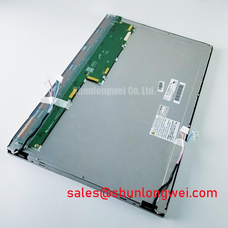
Incoming inspection should distinguish an illumination problem from a panel drive or bonded connection problem before the display is installed in the instrument. For the NEC NL3224AC36-01D, begin with a visual examination under controlled lighting. Look for cracked glass, edge damage, uneven bezel pressure, contaminated connector contacts, and signs that the flexible cable has been sharply folded. The module is categorized as a TFT LCD active matrix color display, while detailed COG, TAB, and ACF construction data is not assigned in the supplied baseline.
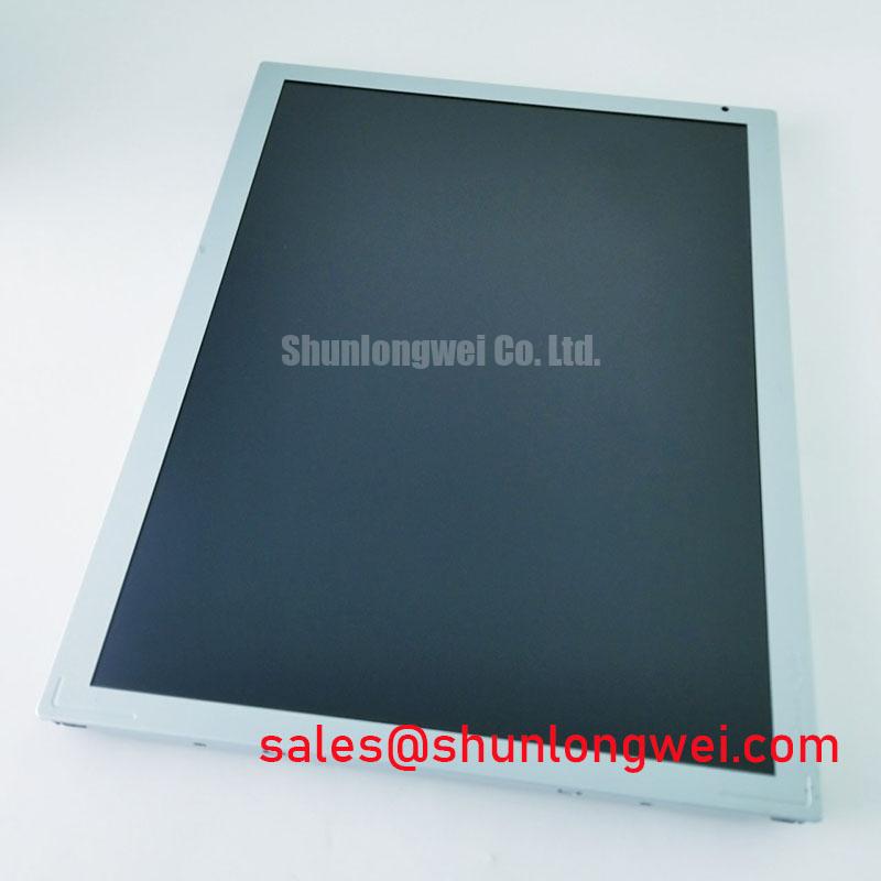
A practical three pattern bench check uses full red, full green, and full blue images, followed by a neutral grayscale image. These patterns help separate color channel errors from illumination nonuniformity and local line defects. A black image can then reveal light leakage, edge glow, or isolated bright points. Record the result with the panel supported on a flat, non stressing surface; pressing the glass or bonded edge during testing can create a temporary visual change that does not represent normal operation.
A flashlight held at approximately forty five degrees can help reveal dark shadows, uneven diffusion, and local regions that do not respond normally to the backlight. This is an observational method, not a proof of a particular internal failure. A shadow that follows the illumination path may relate to the backlight or optical stack, while a fixed vertical or horizontal line that remains visible across different colors should prompt inspection of the panel drive path and bonded edge area.
Cold temperature testing should be gradual. Allow the module and controller to reach the test condition before judging response time, then observe whether the image recovers as the assembly returns toward room temperature. A heater strip should only be evaluated when it is part of the original equipment design and is controlled independently with appropriate thermal protection. Do not attach a heater directly to the LCD glass or flexible cable without mechanical and thermal validation.
FPC reliability depends on bend radius, strain relief, connector lock engagement, and enclosure movement. Route the cable without forcing it against a sharp chassis edge, and confirm that the latch remains fully seated after the bezel is installed. Disconnect instrument power before inserting or removing the display cable to avoid stressing the panel interface during a live connection.
When comparing the NL3224AC36-01D with another display option such as NL12880BC20-02D, compare the complete mechanical outline, active area, connector position, data mapping, mounting features, and backlight interface. Similar industrial display terminology does not establish a drop in replacement relationship.