



Content last revised on September 10, 2026
NL4823BC27 05 Inspection and Integration Guidance
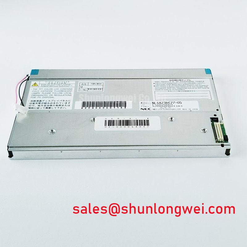
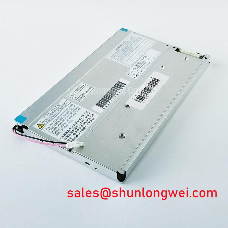
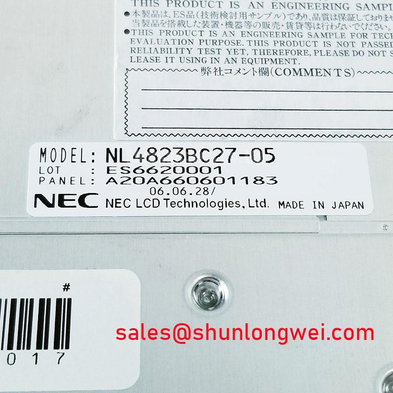
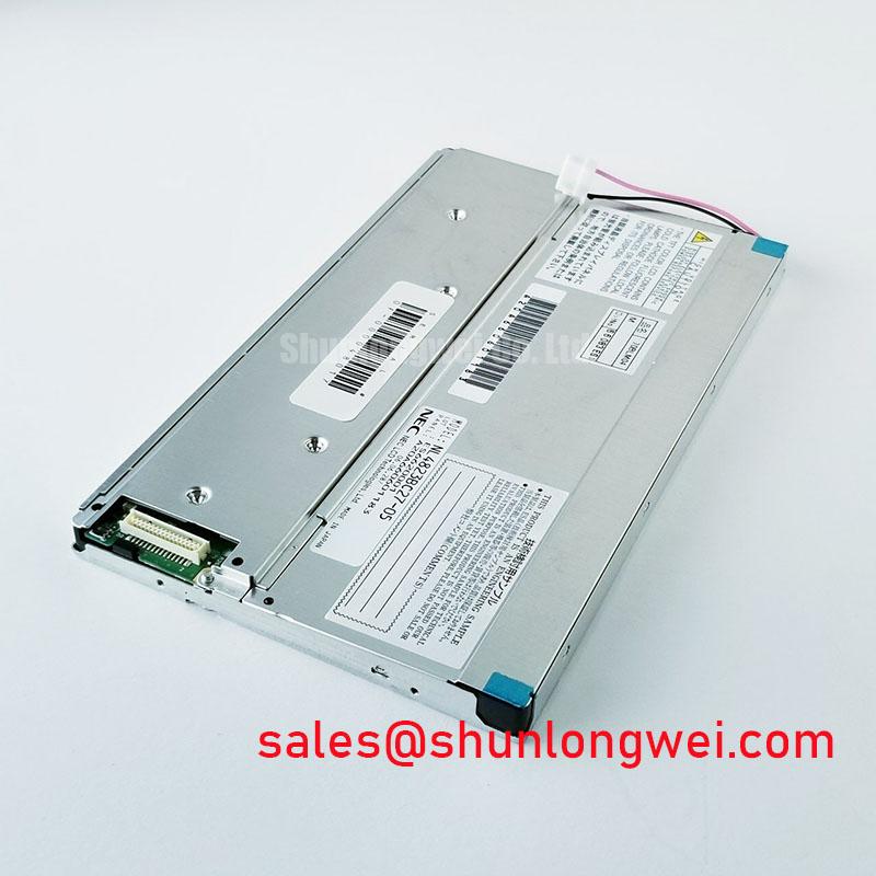
Begin incoming inspection by checking the rear label against the service record, then examine the active area, bezel edges, mounting points, and display cable interface before applying power to the NL4823BC27 05. This NEC unit is identified as an Industrial Grade LCD HMI Panel in a TFT LCD Display Module format. Available product information identifies the product category and module format; the system integrator should verify the original panel documentation for signal interface, supply rails, backlight arrangement, timing values, mechanical dimensions, and environmental ratings before replacement or new equipment integration.
For repair work, the useful first decision is whether the observed defect remains attached to the panel itself or follows the host controller, cable, or power path. A panel can show a stable image while still presenting intermittent artifacts after chassis movement, cable strain, or temperature change. Record the symptom with the existing assembly, inspect the mating connector under magnification, and compare behavior only after the original host signal path has been restored. This approach avoids assigning a display fault to the module when the cause may instead sit in the controller board, harness, grounding arrangement, or backlight supply.
| Item | Available product information | Integration note |
|---|---|---|
| Model | NL4823BC27 05 | Confirm the complete label designation before service release. |
| Manufacturer | NEC | Use the original equipment documentation to confirm host compatibility. |
| Product category | Industrial Grade LCD HMI Panel | Suitable for evaluation in industrial display and operator interface repairs. |
| Module format | TFT LCD Display Module | Verify connector orientation, panel dimensions, interface, and power sequence at system level. |
| Specification status | Product category and module format identified | Use the original NEC documentation for technical acceptance criteria. |
Single Vertical Hairline Defect and Column Signal Path Localization
Use a controlled full screen test image before attempting connector reseating or replacing any adjacent electronics. A practical bench sequence is to present solid red, green, and blue fields, followed by white, mid gray, and black. Observe the panel from normal viewing distance and again from close range. A vertical hairline that stays in the same screen location through every color field can indicate that the defect is local to the display signal path, while a line that changes appearance with image content, cable pressure, or host board movement deserves further investigation across the interface connection and timing source.
A flashlight inspection can help separate apparent illumination irregularity from a line visible in image data. With a dark test pattern active, direct a low angle light across the front surface and inspect the affected region at approximately a forty five degree viewing angle. Surface contamination, pressure marks, polarizer scuffs, and localized optical effects may become easier to distinguish from a stable image line. This is a diagnostic observation rather than proof of a particular internal failure mechanism. The available product information for NL4823BC27 05 does not define internal driver construction, therefore no component level conclusion should be made from the visible symptom alone.
Where the host documentation identifies a differential display interface, signal integrity should be assessed at the transmitter and connector rather than inferred from the image alone. Design Consideration: differential pairs are commonly evaluated as controlled impedance paths, with 100 Ω treated as a general industry reference for many differential links, subject to the actual controller and panel documentation. Clock quality, pair continuity, return path quality, connector retention, and data timing should be checked against a known good host signal path. Clock jitter margin and data hold time are system determined values; they are not published factory specifications in the information available for this NEC module.
Examine the cable latch condition without flexing the display glass or applying leverage to the connector. A cable that appears inserted but is not fully parallel with the mating face can create intermittent line artifacts during vibration or enclosure servicing. 💡 Bench Tip: Disconnect power before handling the display cable, use ESD controls, and seat the cable squarely so the locking feature engages evenly across its width.
If the original panel cannot be retained, replacement assessment should start with the complete mechanical and electrical interface rather than visible similarity. The NL10276BC16 06 can be reviewed as a separate display option during material evaluation, but its suitability must be confirmed from its own documentation and the host equipment requirements. Matching a part family name, connector style, or screen appearance does not establish interchangeability.
Frame Lag and Image Smearing During Low Temperature Equipment Operation
When a display is removed from cold storage or operates in an outdoor industrial enclosure, record the image response after thermal stabilization rather than judging it immediately after power application. Liquid crystal behavior can change with temperature, and apparent frame lag or gray transition smearing may be noticed when the panel temperature differs substantially from the normal operating condition of the equipment. The available official information for NL4823BC27 05 does not publish a temperature range, gray to gray response time, or thermal cycling rating. Those limits must be checked in the original NEC panel documentation before this model is approved for a specific ambient condition.
A useful field comparison is to display scrolling text, alternating grayscale blocks, and a moving cursor after the host controller has reached stable operation. Repeat the observation after the enclosure has equalized toward the expected service temperature. If image persistence changes with temperature but the signal waveform remains consistent, the result may point toward panel response behavior. If the defect appears only while cables or boards are physically disturbed, investigate the harness, connector loading, grounding, and controller output before treating the panel as the sole cause.
Do not infer perimeter seal condition from response speed alone. Edge discoloration, moisture marks, pressure distortion, and changing contrast are separate observations that should be recorded visually. Design Consideration: enclosure sealing, condensation control, cable strain relief, and thermal expansion management should be assessed as a complete assembly because the panel is only one element of the installed display system. The product information supplied for this model does not establish a specific sealant material, low temperature rating, or high temperature endurance claim.
Backlight control also requires separation from pixel response. A fluctuating screen can result from the host dimming command, an illumination power stage, signal timing, or the display module. The proposed range of PWM operation sometimes discussed in industrial equipment is not an official specification for this NEC panel. The system integrator should verify the required backlight control method, dimming input characteristics, permitted frequency range, and duty behavior from the original panel and controller documentation. This is especially important where low frequency dimming can be visually objectionable in text interfaces or interact with surrounding equipment.
For a high voltage substation protection or SCADA dispatch console, the panel should be evaluated as part of the complete human machine interface assembly. Screen readability, enclosure temperature, front surface condition, controller timing, alarm visibility, and power recovery behavior should be tested on the actual console architecture. The fact that a TFT module is categorized for industrial HMI use does not independently prove compatibility with any particular protection terminal or dispatch workstation.
Backlight Noise, Illumination Stability, and Unverified Driver Assumptions
Start acoustic troubleshooting with the display assembly powered in its normal host equipment, then determine whether the audible sound changes with brightness command, image content, or physical proximity to the power board. A buzz perceived near a panel can originate from a backlight driver, power conversion component, enclosure resonance, or another board within the console. It should not be attributed to the NL4823BC27 05 until the source has been isolated with the panel and driver arrangement defined by the original equipment.
The official information provided for this model identifies it as a TFT LCD display module but does not verify whether the backlight uses CCFL or LED technology. It also does not publish cold ignition voltage, dimming ratio, PWM frequency, constant current requirements, brightness, color temperature, luminous decay, or operating life. For that reason, values sometimes associated with legacy CCFL ignition circuits, LED dimming behavior, or backlight life testing must not be represented as specifications of this NEC model. The system integrator should verify the required supply voltage and illumination architecture from the original panel documentation.
During bench inspection, use full white, neutral gray, and black patterns to assess illumination consistency. Look for localized dim regions, edge brightening, unstable brightness during controller commands, intermittent illumination after movement, and changes after the display has remained powered. These observations help establish whether the symptom follows the image source or the illumination path. Where a separate driver board is present, inspect its connector retention, power input stability, enable signal behavior, and grounding relationship to the host chassis.
Visual flicker must be evaluated in the actual viewing environment. A camera can exaggerate or invent banding because its shutter timing interacts with display refresh and illumination modulation. Direct human observation, a stable reference panel, and scope measurements at approved test points provide more useful evidence. Engineering Recommendation: evaluate dimming behavior with the original host controller, under the intended display content and ambient lighting, then validate any corrective action through repeated functional testing rather than a single visual check.
Claims of illumination half life, mean time between failures, or guaranteed acoustic performance require an applicable factory specification or a documented external test source. No such life or reliability figure is established in the available information supplied for NL4823BC27 05. Procurement and maintenance teams can instead preserve traceability by recording the panel label, host equipment model, observed illumination state, connector condition, replacement date, and results of the final functional test.
Pixel Jitter and Horizontal Noise Near Motor Drive Installations
When horizontal white lines, pixel jitter, or intermittent noise bands appear near motor drives, begin by comparing the display with the drive inactive and active while maintaining normal safety procedures for the equipment. Note whether the disturbance tracks motor speed changes, switching events, contactor operation, cabinet door position, cable routing, or ground bonding changes. A visible artifact can be caused by conducted noise, radiated coupling, a weak return path, an unstable controller supply, or a signal cable issue. It is not valid to declare an EMC rating or immunity level for the NL4823BC27 05 from the available product information.
For installations close to variable frequency motor equipment, the cable and chassis arrangement deserve careful inspection. Design Consideration: maintaining a continuous shield termination where the system cable design supports it, minimizing unnecessary signal loop area, and preserving the intended chassis return path can reduce susceptibility to coupled interference. The final grounding method, ferrite selection, cable routing, and termination treatment are system determined and should be verified through measurements on the installed equipment. No specific shield coverage, ferrite value, cable length, or motor voltage compatibility is an official specification of this NEC display module.
Inspect both ends of the display cable for uneven insertion, damaged locking features, trapped cable sections, sharp bends, and routing adjacent to high energy conductors. Then inspect the host controller power rail and display output against a known good signal path. If horizontal noise changes when the cable is repositioned, that result may indicate coupling or connection sensitivity, but it does not by itself identify the exact source. An oscilloscope comparison at appropriate approved points can help distinguish unstable data timing from common mode disturbance or supply related behavior.
The display module should be protected from unnecessary mechanical stress during these checks. Avoid pressing the active area to force a symptom, because pressure can create temporary optical changes that complicate diagnosis. Use static images and repeatable controller conditions, document the screen location of the artifact, and verify whether it persists after the original cable routing and ground connections are restored.
For broader reference when planning display signal checks, enclosure integration, and industrial TFT fault isolation, consult The Ultimate Guide to Industrial TFT LCD Technology. Apply its general integration principles alongside the original NEC documentation and the actual host system evidence, since the available product information for NL4823BC27 05 does not define independent EMC compliance, interface timing, or environmental qualification values.



