

Content last revised on September 10, 2026
Suppressing Pixel Jitter and Horizontal White Lines Induced by Adjacent 400V Motor Drives
Begin a display fault investigation with the equipment de-energized. Check that the display cable is fully seated, that the connector latch or retention hardware is intact, and that the cable route has not been moved closer to motor-drive output wiring during previous cabinet work. Pixel jitter, intermittent horizontal bands, or unstable image timing can have several possible causes, including signal integrity problems, grounding arrangement, connector condition, power disturbance, or a fault elsewhere in the display system.
Design Consideration: Where the host equipment uses LVDS or another differential display interface, the cable shield and chassis bonding arrangement should be reviewed as a complete system. A shield that is terminated inconsistently at the panel and controller can allow common-mode interference to enter the signal path. A fully shielded cable assembly may be evaluated where the original equipment design supports it, but the correct termination method must follow the controller and panel documentation rather than a generic wiring assumption.
Near variable-frequency motor drives, route display cabling separately from high-current switching conductors wherever the cabinet layout permits. Avoid unnecessary cable loops and prevent the display cable from running parallel to drive output conductors for long distances. If separation is limited, the system engineer should evaluate the effect with the motor drive operating through its normal switching states. Common-mode ferrite suppression may be considered only after confirming cable impedance, connector compatibility, grounding, and thermal conditions. Ferrite selection is system dependent and should be validated with the known-good signal path.
For a suspected noise-related display fault, compare the affected unit with a known-good panel or controller under the same operating condition. An oscilloscope can help determine whether the disturbance is present on the supply rail, the display interface, or the chassis reference. The result should be recorded with the motor drive stopped and running, because a clean image at idle does not establish stable operation during switching.
Claims such as a contrast ratio above 500:1 at 50,000 lux, or the presence of a particular anti-glare coating, are not confirmed in the supplied specification record for this model. Daylight readability must therefore be verified from the original panel data and by evaluating the assembled HMI behind its actual window, bezel, and protective cover. A railway passenger information system or cab signalling display may require additional optical validation because reflections can originate from the enclosure window even when the panel surface itself appears acceptable.
For a broader review of cable routing, enclosure conditions, grounding, and HMI service practices, engineers can consult Industrial Display and HMI Solutions as a system-level reference.
Suppressing Localized Thermal Gradients to Prevent Chronic Optical Yellowing and Color Shift
Inspect the display opening, rear clearance, and nearby heat sources before fitting the NL6448BC33-70K into a cabinet. A narrow bezel, poorly vented enclosure, drive heat, or direct contact with a warm metal panel can create a temperature gradient across the display assembly. Uneven thermal conditions may appear as localized brightness or color differences, but the observation alone does not identify the failed part. The panel, backlight system, optical layers, controller, and enclosure should be assessed separately.
Design Consideration: An aluminum heat spreader rail can be evaluated along a narrow display edge when the mechanical design creates a localized hot area. The rail must not impose concentrated pressure on the glass or interfere with the display frame, connector, or rear clearance. Its value should be checked by measuring temperatures at several points during the equipment’s normal duty cycle. The final thermal path is determined by the cabinet, mounting frame, airflow, adjacent components, and display construction.
The supplied factory data does not confirm an LED backlight, constant-current backlight driver, L70 or B50 rating, a 50,000-hour MTBF value, or an optical material specification for this model. Those values must not be assumed from the model number. If the original documentation identifies an LED backlight, the service engineer should verify the backlight supply, current-control method, enable signal, dimming method, and protection behavior before connecting a replacement assembly.
Backlight open-circuit or short-circuit behavior should be diagnosed from the equipment’s driver output and protection records rather than from an assumed panel threshold. An open circuit may cause the driver to enter a protective state, while a wiring short, connector contamination, or controller fault may produce a similar no-light symptom. Measure only with instruments and procedures suitable for the equipment voltage, and compare readings with the service manual or a known-good assembly.
Cold-start behavior also requires system validation. If the display is installed in an outdoor cabinet or an unheated vehicle compartment, designers should evaluate startup response, condensation risk, heater operation, and enclosure pressure equalization across the actual temperature cycle. The panel’s permitted operating and storage ranges must come from the original NEC documentation. Response-time compensation, PWM dimming frequency, and flicker performance are properties of the complete panel and backlight driver combination, not confirmed specifications of the model record supplied here.
When comparing a replacement candidate, the NL10276BC16-06 may be reviewed as a separate display reference, but mechanical dimensions, interface signals, electrical ratings, and optical behavior must be checked independently. Similar application language or a similar display category does not establish interchangeability.
Surface Anti-Glare and Anti-Reflective Treatment for High Ambient Readability
Evaluate the complete optical stack at the installation site rather than judging the bare display on a workbench. Record the viewing direction, enclosure-window reflections, operator position, sunlight angle, status-lamp reflections, and any protective film used by the equipment manufacturer. The supplied specification context does not confirm AG etching, AR treatment, surface hardness, haze, luminance, grayscale behavior, or a specific viewing-angle figure for the NL6448BC33-70K.
A TN display can show angle-dependent grayscale changes, while IPS or MVA technologies may provide different viewing characteristics. The panel technology and viewing cone must be verified from the original NEC documentation; the supplied record identifies the unit only as a TFT-LCD display module. A viewing specification such as 85°/85°/85°/85° must not be assigned to this model without documentary confirmation.
In high ambient light, AG treatment can reduce mirror-like reflections but may also alter perceived sharpness or black-level clarity. AR treatment can reduce certain reflected components but depends on the surface stack, cover glass, illumination geometry, and cleanliness. The correct choice is an engineering evaluation of the installed assembly. Do not add a film or window coating until its optical compatibility, adhesive behavior, cleaning method, and temperature range have been confirmed.
If the controller uses a differential display interface, trace impedance, pair matching, and skew should be designed from the controller and panel interface specification. Values such as 100 Ω ± 10% or a particular picosecond skew budget are not confirmed factory parameters in the supplied data for this model. They may be applicable to a particular interface architecture, but the system designer must verify the required electrical targets with the original documentation and validate the eye opening at the panel connector.
For railway passenger information or cab signalling equipment, readability testing should include direct sun, tunnel exit transitions, night operation, operator viewing angle, and the installed protective window. The panel should also be checked after cleaning because residue, fine abrasion, and an incorrectly fitted overlay can change reflection behavior. A replacement assessment is complete only when the image remains legible under the actual cabin or passenger-area lighting conditions.
Preventing Micro-Twist Mechanical Stress and Glass-Substrate Driver Damage
Before removing the existing display, photograph the cable orientation, frame position, gasket contact area, and fastener locations. Release the panel evenly and support the glass assembly without twisting it around a single corner. During installation, the mounting frame should sit flat, the gasket should contact continuously, and the fasteners should be tightened progressively so that the force is distributed rather than concentrated at one edge.
⚠️ Maintenance Note: Disconnect power before inserting or removing the display cable, and periodically inspect the cabinet airflow path and sealing gasket for dust buildup, compression damage, or loss of contact.
A dark area, a vertical line, an intermittent color region, or a completely unlit image can originate from different sections of the display system. Begin with a controlled primary-color bench test using red, green, and blue images from the approved controller. Observe whether the defect remains fixed on the glass, changes with image content, appears only after warming, or changes when the cable is disturbed without applying force to the panel. These observations help separate image-data problems from optical or backlight behavior, but they do not prove a particular internal failure mode.
A flashlight inspection at approximately a 45-degree angle can be used as a visual aid while the panel displays a dark image. A faint image under oblique light may suggest that image data is present while the illumination path requires further checking. No visible image can also result from controller power, interface timing, enable sequencing, or panel damage. Verify the signal path against a known-good assembly and avoid pressing the glass or bonded driver region during diagnosis.
Thermal cycling and condensation deserve attention in vehicle and outdoor HMI service. Allow a cold display to reach a controlled, dry condition before energizing it when condensation may be present. Check the enclosure seal, drain path, rear ventilation, and mounting surface for evidence of moisture. The acceptable temperature range and startup limits must be taken from the NEC documentation for the specific production revision.
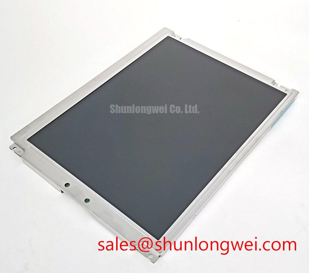
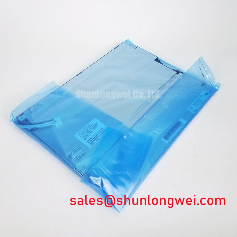
For procurement, identify the unit as NEC NL6448BC33-70K, an Industrial Grade LCD/HMI Panel classified as a TFT-LCD Display Module. Before release to field service, match the original connector arrangement, mechanical envelope, optical requirements, controller compatibility, and documented electrical ratings. Where any of these records are unavailable, obtain the original panel documentation or compare the complete assembly under controlled bench conditions rather than relying on model-name similarity.