
Content last revised on October 5, 2026
Chassis Fastening and Optical Mura Checks
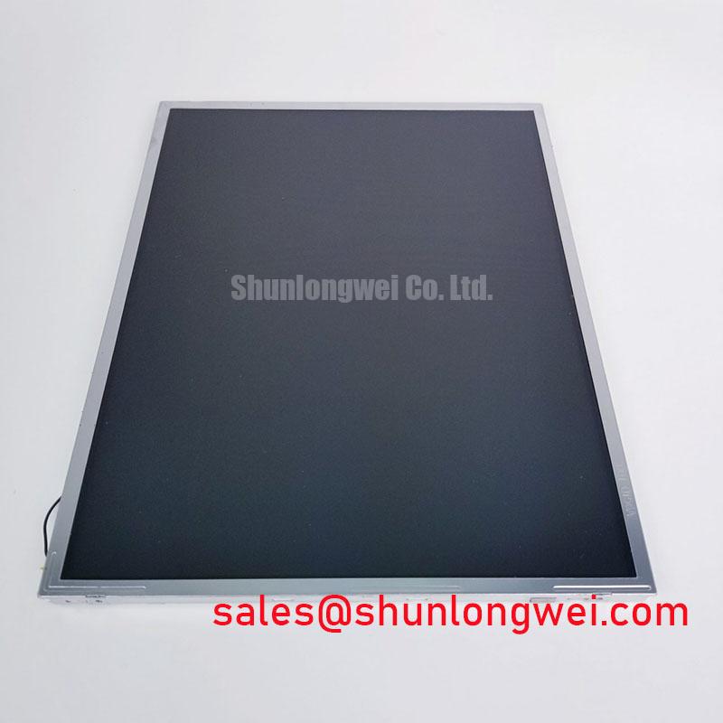
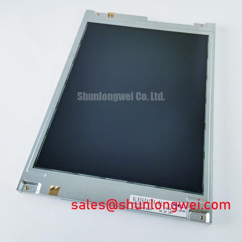
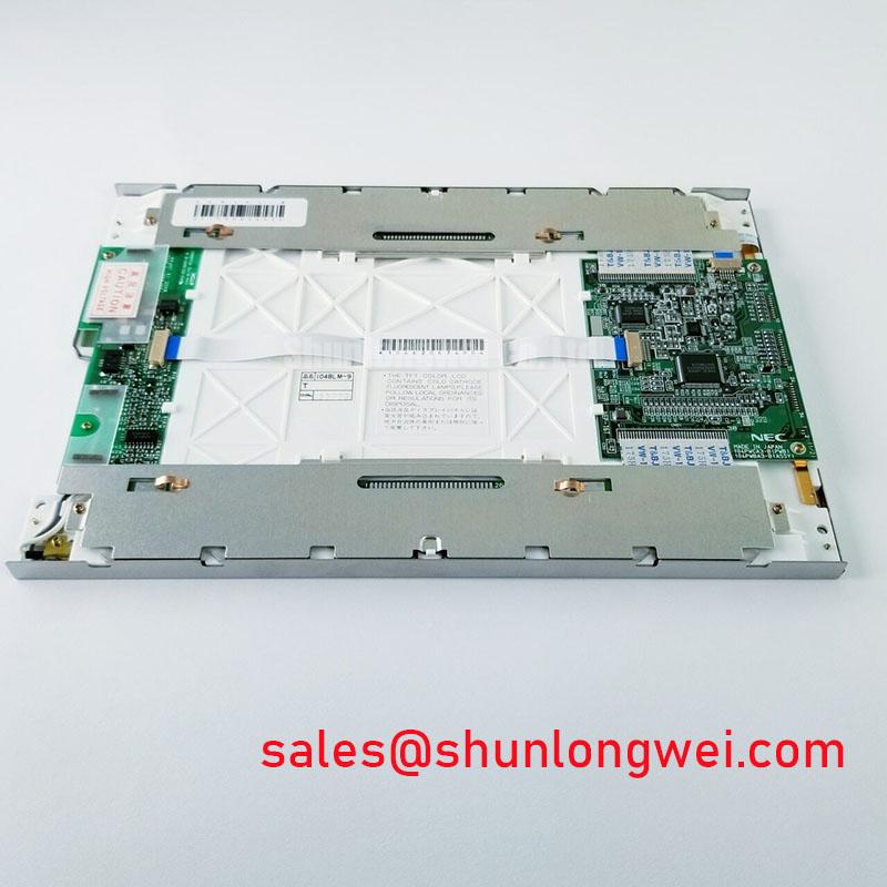
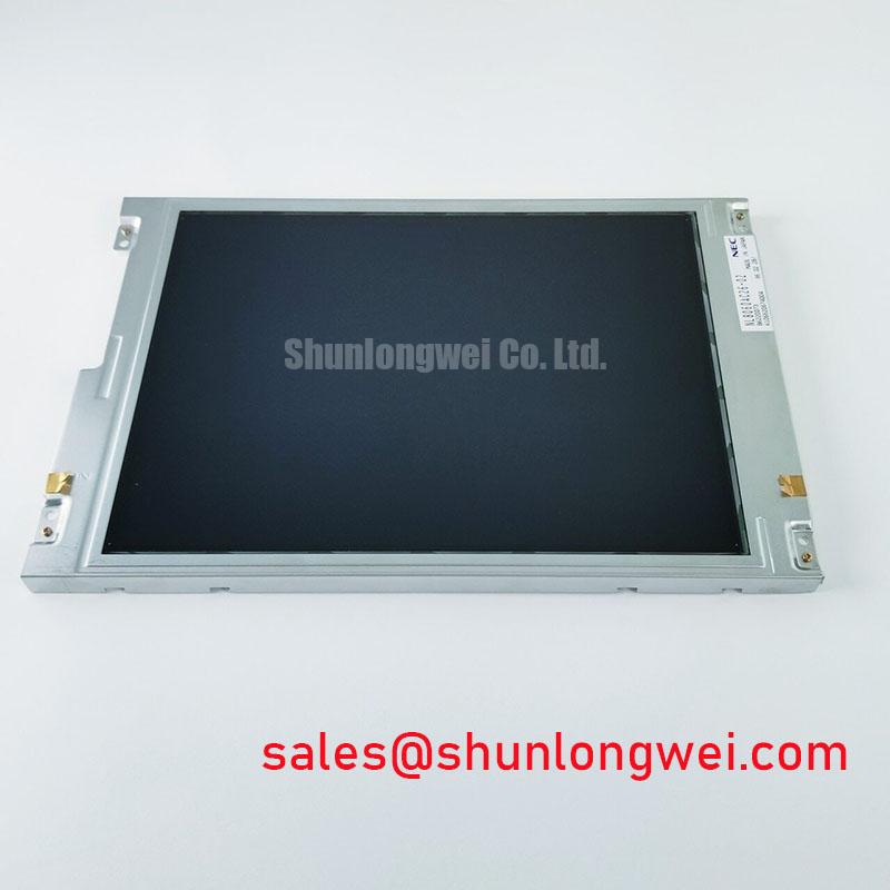
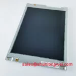
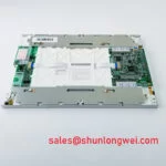
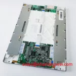
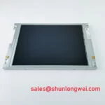
Inspect the connector, mounting points, and active display area of the NL8060AC26-02 before connecting it to a service fixture. This NEC TFT-LCD display module is identified as an industrial LCD/HMI panel (Official Factory Specification). For a repair or enclosure redesign, the model identity is the starting point; electrical connections, backlight requirements, and mechanical clearances still need to be checked against the original panel documentation and the equipment drawing.
Place the module in the intended bezel without tightening the retainers. Check that the opening clears the visible area, the chassis sits flat, and cables can leave the connector without being folded against the enclosure. These checks matter in a replacement job because a display that fits the nominal opening can still contact a bezel lip or sit unevenly on its supports. Record the mounting-hole locations and the relationship between the visible area and the housing datum before transferring an existing bracket design.
Localized light or dark patches can change as the bezel is fitted. As a Design Consideration, compare a uniform test image with the module supported freely and then with the enclosure assembled. If a patch appears only after assembly, inspect contact points, gasket placement, and retainer loading before treating it as an electrical fault. Use the fastener specification for the actual chassis hardware; the NL8060AC26-02 identity alone does not establish an M3 torque limit or a particular tightening pattern.
For equipment exposed to cold starts, evaluate image response at the temperatures specified for the completed system. A slow transition on a moving test pattern should be distinguished from missed video data by repeating the test after the assembly reaches a stable operating temperature. Do not add a heater strip on the assumption that this panel requires one. Any heater, sensor, and control sequence belongs to the enclosure design and should be checked against the panel’s documented temperature limits.
Physical compatibility is also a separate question from model-family similarity. An engineer considering NL10276BC16-06 for an equipment repair should compare drawings, connector assignments, video timing, and backlight requirements with those of the NL8060AC26-02 before calling the change a direct replacement. Matching an enclosure opening does not establish electrical interchangeability. A heavy mining shovel telematics display, for example, may be a candidate application to evaluate, but its vibration mounting and enclosure sealing have to be assessed at equipment level.
Edge Heating and Video Signal Integrity
Run the assembled display on a stable test image long enough to identify whether enclosure surfaces or nearby electronics create a concentrated warm area. Check temperatures at accessible chassis locations and compare them with the limits in the original panel and equipment documentation. As a Design Consideration, an enclosure designer may evaluate heat-spreading features when neighboring power electronics warm one edge of the display. Their size and placement should follow measurements in the actual housing rather than an assumed internal optical construction of this module.
Inspect the host board schematic before selecting or replacing the video cable. The supplied product identity does not establish an LVDS or TTL pinout, clock rate, supply voltage, or JEIDA/VESA mapping. Those details must come from the original panel documentation and the host design. A visually compatible connector is insufficient evidence: the system integrator should verify power pins, grounds, control signals, and video assignments before energizing the assembly.
If the documented interface uses differential video pairs, keep each pair routed and terminated as required by the transmitter and receiver documentation. 💡 Pro Tip: Keep documented differential pairs closely matched through the cable and board transition, then verify clock and data quality at the panel connector before attributing intermittent pixels to the LCD. This is an Engineering Recommendation, not a published routing limit for the NL8060AC26-02. Pair impedance, skew, and acceptable jitter must be determined from the actual interface specification and measured in the installed system.
Intermittent color errors near operating servo drives warrant a controlled comparison: display the same test pattern with nearby equipment inactive and active, then inspect the video signals and cable grounding at accessible test points. Such a result may suggest coupling into the signal path, but it does not establish a panel fault or an EMC compliance rating. Screen grounding, cable routing, and filtering are equipment-level Design Considerations to validate in the completed assembly.
For broader explanations of panel interfaces and optical behavior, The Ultimate Guide to Industrial TFT LCD Technology provides related background. For this repair, however, the original NL8060AC26-02 documentation remains the authority for its pin assignments and operating limits.
Backlight Identification and Dimming Checks
Identify the installed backlight circuit from the original panel documentation and equipment schematic before attaching a driver. The available product identification confirms a TFT-LCD display module (Official Factory Specification), but it does not confirm the backlight technology, drive current, ignition behavior, dimming input, or protection outputs. Treating an unfamiliar backlight connector as an LED connector could put the wrong circuit on the wrong pins.
During bench diagnosis, separate image formation from illumination. With the documented supplies applied through an appropriate fixture, check whether a faint image is present when the screen appears dark. If image data is visible without normal illumination, examine the documented backlight supply path, driver enable signal, cable seating, and any available fault indication. This observation narrows the investigation; it does not by itself prove that the backlight or driver has failed.
Where the equipment uses a separately controlled backlight driver, compare its start sequence and dimming behavior with the host schematic. A constant-current control principle may be relevant to a documented LED implementation, while a different documented backlight requires its specified drive circuit. PWM range, open-circuit response, short-circuit protection, and fault-output behavior are driver-specific values to verify rather than attributes to assume for the NL8060AC26-02. No backlight operating-life figure can be inferred from the panel model name.
The NL10276BC30-24D is another NEC display model that may appear in a broader display sourcing review. Its listing does not establish that it is a backlight driver for this panel or that its circuitry is compatible. Compare the two models only against their respective documentation and the intended host hardware.
Touch operation and surface visibility also depend on the assembled equipment. If a repair includes a touch overlay, test glove and wet-surface behavior on that overlay and its controller; neither feature is established by the LCD module identity. Likewise, verify any anti-glare or anti-reflective treatment from the actual cover assembly documentation before specifying readability in strong ambient light.
Vertical Line Localization and Timing Verification
Display solid primary-color images followed by a grayscale ramp, and record whether a vertical line remains fixed at the same screen position. Repeat the observation after reseating accessible cables with power removed and after checking the source image at the host output. A fixed line can have more than one origin, including the source path, a connector fault, or the display assembly. The test should locate the fault boundary rather than assign a cause from appearance alone.
When the screen is dark, use a handheld light at an oblique angle to see whether image detail is still being formed. Compare that observation with the solid-color tests: missing illumination and missing pixel data call for different follow-up measurements. Avoid pressing on the visible area to provoke a change; mechanical pressure can alter the image while adding no reliable evidence about the original fault.
For washed-out tones or irregular grayscale steps, check the host’s output format and timing before investigating panel-side grayscale generation. Gamma behavior and timing-controller voltages cannot be assigned numerical targets without the original service information. Compare the same known test pattern on a known-good signal path, then measure only at test points identified by the applicable circuit documentation. A color-order mismatch may also warrant checking the documented data mapping rather than adjusting image settings to conceal it.
If line defects appear only after warm-up or when nearby equipment switches, capture the video clock and data at accessible points under both conditions. Assess jitter, signal levels, and setup and hold timing against the documented transmitter and panel interface requirements. Keep the panel supply and backlight sequence under observation during the same test so that a transient power event is not mistaken for a video fault. These measurements give the repair engineer a basis for deciding whether to investigate the host, cable, driver circuitry, or NL8060AC26-02 module next.