

Content last revised on September 10, 2026
TTL 24-Bit Digital RGB Bus Synchronization and Logic Power Rail Verification
For a suspected replacement in a radar display, bridge console, industrial HMI, or other monitoring terminal, begin with the host board rather than connecting the panel immediately. Record the existing panel’s connector keying, pin names, cable direction, display-enable behavior, clock relationship, and power-on sequence. Although a 24-bit RGB interface is included in the requested evaluation scope, the supplied product record does not confirm that this exact NEC panel uses a TTL RGB, LVDS, or another interface. Treat the interface as a system compatibility item requiring documentation-based verification.
The logic supply must also be confirmed from the original NEC panel documentation. Do not assume a 3.3 V or 5.0 V rail because both values are common in industrial display assemblies. The controller output level, panel input threshold, enable polarity, reset behavior, and allowable rise-time window must be matched to the panel documentation. A bench supply with current limiting can support initial evaluation, but the measured current should be compared with a known-good unit or the documented specification rather than used as an isolated pass or fail criterion.
When the host uses a parallel RGB bus, verify red, green, and blue bit order together with pixel-clock polarity and synchronization timing. JEIDA and VESA terminology is primarily associated with serial LVDS mapping, so a service engineer should not transfer an LVDS mapping assumption to a TTL interface without checking the schematic and panel pin definition. Incorrect bit ordering can produce color distortion, while an unsuitable clock edge or timing relationship may appear as unstable imagery, split-screen content, or intermittent loss of synchronization. These symptoms can also involve the controller, cable, connector, or power sequencing, so diagnosis should compare the complete known-good signal path.
For a serial display link, the transmitter and receiver must share the same lane arrangement, data mapping, clock arrangement, and signal polarity. Route high-speed pairs as a controlled differential interface according to the system PCB rules, with a continuous reference plane and minimized discontinuities. The frequently used 100-ohm differential target is a system-level design consideration, not a confirmed factory parameter for NL8060BC26-17. Engineers should validate impedance, pair continuity, skew, and clock quality with the appropriate test method before attributing image defects to the panel.
Temperature testing deserves separate attention when the display is installed in an exposed console. Compare cold-start image appearance, synchronization stability, and response time against the original unit across the approved operating range. The supplied factory data does not provide a temperature range or a cold-start compensation specification for this model, so no guaranteed low-temperature behavior should be assigned to it. For a replacement study, monitor the supply rail, display-enable timing, pixel clock, and frame stability while the enclosure reaches its intended environmental condition.
For a same-family sourcing comparison, engineers may review NL10276BC16-06 as a separate display option. It should not be treated as an automatic substitute: resolution, interface, connector assignment, optical stack, mechanical envelope, and backlight requirements still require a side-by-side verification.
High-Voltage Striking Potential and Secondary Coil Insulation Testing
The supplied information identifies the product as a TFT-LCD display module but does not confirm whether its illumination system uses a cold-cathode fluorescent lamp, an LED assembly, or an external backlight arrangement. Consequently, high-voltage striking values, secondary-coil insulation requirements, PWM performance, luminance half-life, and failure thresholds cannot be presented as official specifications for NL8060BC26-17.
If the original equipment documentation identifies a high-voltage fluorescent backlight, the inverter and lamp circuit must be tested as a complete assembly. Inspect the high-voltage cable routing, connector condition, insulation clearance, return path, and inverter feedback wiring. Use an appropriately rated test setup and follow the equipment manufacturer’s safety procedure; do not probe an energized ignition circuit with ordinary handheld instruments. A visible flash, audible noise, or repeated shutdown may involve the inverter, lamp, wiring, protection circuit, or panel interface, and should be isolated through controlled substitution and waveform observation.
If the documented assembly uses an LED backlight, the system integrator should verify the required constant-current driver characteristics from the original panel documentation. The driver’s output compliance, open-load response, short-circuit protection, thermal behavior, enable logic, and dimming input must be compatible with the display. A replacement LED driver should not be selected solely by matching connector position or nominal supply voltage. A driver that regulates incorrectly can create uneven brightness, delayed start, intermittent shutdown, or stress on the backlight circuit.
PWM dimming should be evaluated for visible flicker, acoustic interaction with mechanical structures, and brightness linearity across the operating range. The requested engineering scope refers to a 200 Hz to 1 kHz evaluation range, but this is not a confirmed parameter of the NEC module. The suitable frequency, polarity, duty-cycle response, and minimum effective duty cycle must be established from the actual panel or backlight driver documentation. Test the dimming signal at the panel input while observing optical output and the driver fault line, if one is provided.
A claimed 50,000-hour brightness-maintenance or MTBF figure must come from a traceable manufacturer specification or reliability document for the exact assembly and test conditions. No such lifetime figure is included in the supplied factory record, so it should not be used as an assured characteristic of this product page. For procurement, request the applicable optical lifetime definition, ambient temperature, drive current, and brightness-retention criterion before using a service-life figure in a maintenance plan.
Single Vertical Hairline Defect and Sub-Pixel Column Driver Open-Circuit Localization
A single vertical line on the screen should be investigated without assigning one cause immediately. First confirm whether the line remains fixed when the displayed image changes. Run solid red, green, blue, white, black, and gray fields from a known-good controller. Record whether the defect changes with temperature, cable movement, brightness setting, or input timing. This separates a persistent panel-area defect from a possible signal, connector, or controller problem, but it does not by itself establish the failed component.
Next, inspect the connector and cable under power-off conditions, checking for contamination, uneven contact pressure, damaged latches, or a cable that is not fully seated. Reconnect only after the system is isolated from its power source. A line that changes when the cable is disturbed may indicate an interconnect or signal-integrity issue, while a stable line through multiple sources may justify further panel-level evaluation.
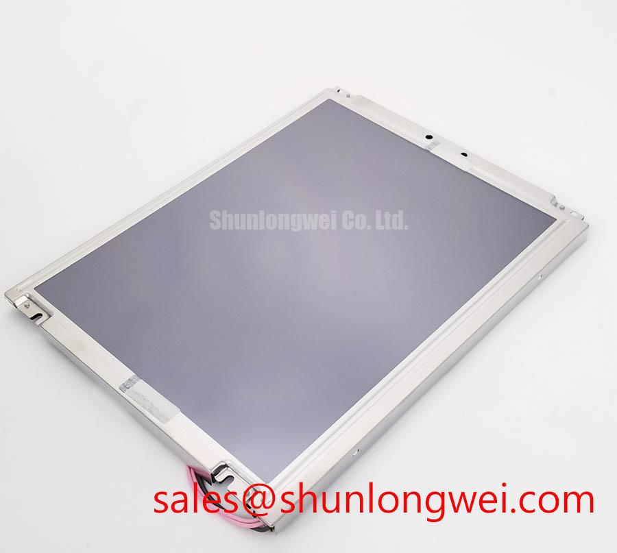
A 45-degree flashlight inspection can help distinguish an illuminated image fault from a surface or backlight symptom. With the display unpowered, use oblique light to inspect the front surface, bezel interface, and visible glass area for scratches, pressure marks, or localized shadowing. This method is a visual aid, not proof of a COG driver fracture or column-driver open circuit. Avoid pressing the glass or bezel because mechanical pressure can change the symptom and compromise the diagnostic result.
Use the primary-color sequence again after the panel has reached a stable operating condition. A line visible in every color may require panel-side investigation, while color-dependent behavior can point toward data mapping, timing, or individual sub-pixel drive paths. The correct diagnostic boundary remains the complete module assembly because the supplied factory record does not provide a public column-driver map, sub-pixel test point, or internal repair procedure.
Outdoor readability must be assessed with the actual cover glass, window, hood, and ambient-light direction used by the equipment. The supplied data does not confirm a contrast ratio above 500:1 at 50,000 lux, nor does it confirm an anti-glare or anti-reflective surface treatment. Those values should be measured or verified from the original documentation under defined conditions. For a harsh marine radar or navigation bridge console, also evaluate salt-contaminated surfaces, condensation, viewing angle, and enclosure sealing as system-level factors rather than assigning environmental certification to the display module itself.
For broader maintenance planning, the Industrial Display and HMI Solutions reference can support enclosure, inspection, and environmental test planning. It does not replace the exact NEC panel specification or the equipment manufacturer’s service procedure.
Thermal Expansion Clearance Sizing across Heavy Industrial Metal Enclosure Cutouts
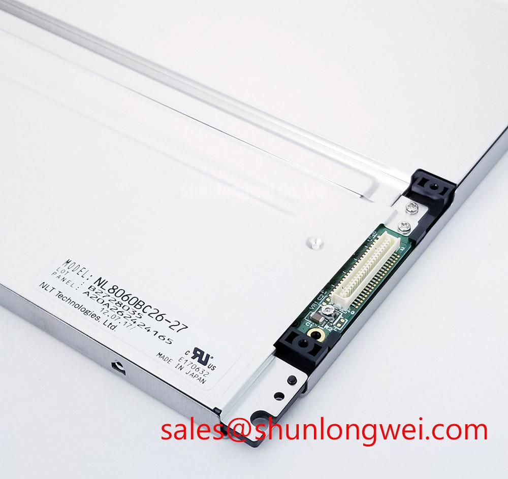
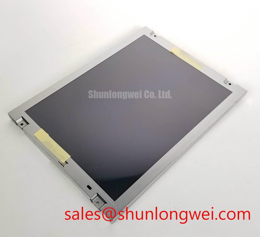
Before mechanical installation, compare the replacement module’s documented outline drawing with the existing cutout, bezel, gasket, cable bend area, and fastener positions. No outside dimensions, active-area dimensions, bezel envelope, or hole pattern are included in the supplied factory parameters for NL8060BC26-17. The panel should therefore not be machined into a metal enclosure until the original drawing has been obtained and checked against the measured equipment opening.
Metal chassis expansion, gasket compression, cable strain, and bezel loading should be considered together. The display must be supported evenly without allowing the enclosure to press directly against the visible glass or active area. Any clearance, gasket thickness, or fastener torque must come from the module drawing or equipment service documentation. A cross-pattern tightening method may help distribute mechanical load, but a specific M3 torque range cannot be stated as an official value for this NEC model without a documented source.
During a powered inspection, display a uniform dark field and then uniform gray and white fields while checking for corner shadows, uneven brightness, colored patches, or changes caused by gentle enclosure movement. These observations can reveal mechanical stress or optical non-uniformity, but they do not identify a single internal cause. If the appearance changes after fastening, release the assembly and reassess the bezel contact, gasket placement, cable routing, and chassis flatness.
Backlight thermal behavior should be validated with the intended driver and enclosure airflow. The available product record does not confirm LED backlight construction, a 50,000-hour brightness-retention rating, thermal derating data, or an MTBF curve. Those characteristics must be obtained for the exact module revision before they are used in a marine console maintenance forecast. Designers should verify steady-state temperature, startup behavior, dimming response, and fault output at the equipment level.
🔧 Bench Diagnostic: Disconnect power before removing or inserting the display cable, and verify connector orientation before the next controlled power-up.
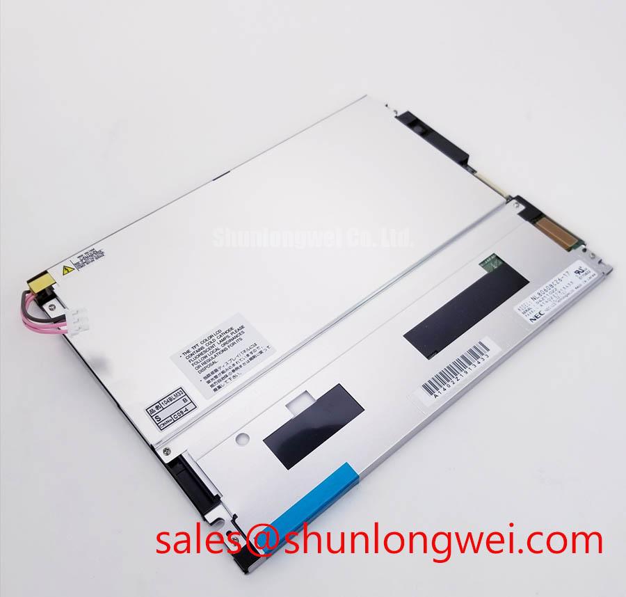
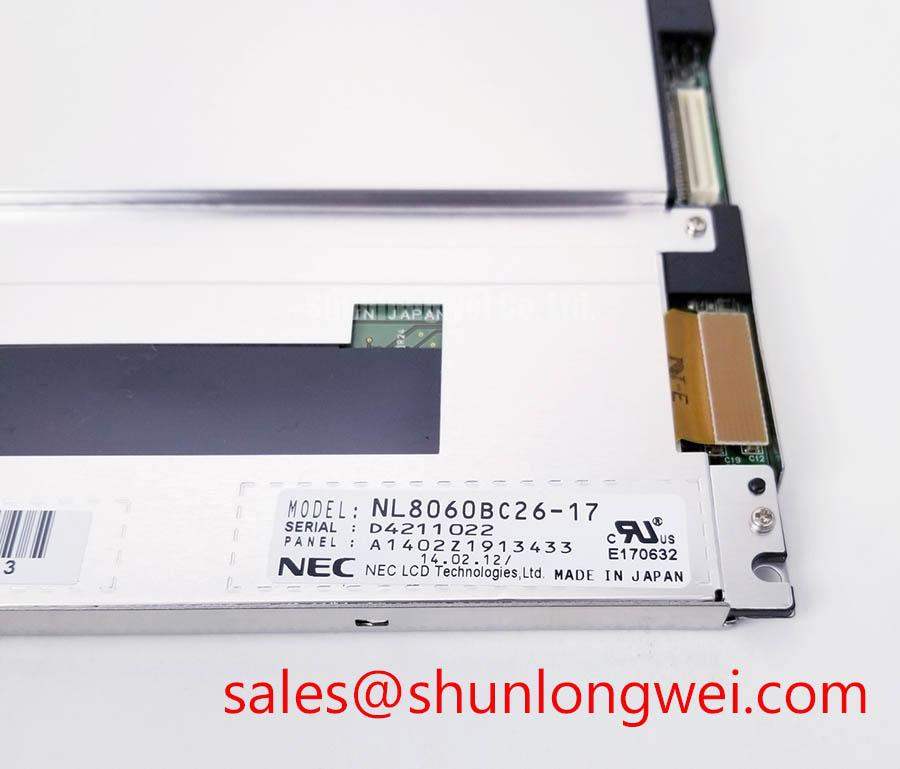
When the mechanical, electrical, and optical checks are complete, document the panel label, revision marking, connector details, measured outline, controller settings, and observed image behavior in the service record. That evidence gives procurement and repair teams a defensible basis for evaluating NL8060BC26-17 against the installed assembly without treating unconfirmed interface or lifetime data as factory guarantees.