

Content last revised on September 18, 2026
Transient Dynamics and Electrical Design: Critical Rate of Rise of Off State Voltage on PD200KN16
In a high voltage three phase motor solid state soft starter, the first practical task is to establish whether the replacement module is being used within the original voltage and current boundary. The 1600.0 V voltage rating and 200.0 A current rating are official product specifications, not a complete system operating prescription. The system designer must compare these ratings with the line voltage, transient conditions, motor starting profile, switching arrangement, protective device coordination, and enclosure cooling conditions.
A rapid rise in off state voltage can interact with stray capacitance, wiring inductance, and the trigger circuit. This is a design consideration when a thyristor based soft starter shows unexplained firing, uneven phase conduction, or repeated fuse operation during commissioning. An RC snubber, damping network, or series saturable reactor may be evaluated where the original circuit documentation calls for one. The resistor and capacitor values must be selected from the actual circuit waveform, device application data, insulation requirements, and measured transient margin. They should not be inferred from the PD200KN16 model number alone.
Use an oscilloscope with suitable high voltage differential measurement equipment to compare the three phase voltage waveforms during energization and controlled starting. The objective is to observe whether an abnormal voltage rise, ringing pattern, or phase imbalance is present. The result should be assessed against the original soft starter design limits and the applicable SanRex application information. A waveform anomaly does not prove that the module alone is defective; gate drive timing, trigger isolation, line impedance, motor condition, and upstream protection can produce similar symptoms.
Fuse coordination requires the actual semiconductor fuse data and the module’s full withstand information. The confirmed product data supplied here does not include an I²t coordination table, surge current rating, or repetitive peak off state voltage specification. For this reason, the fuse must not be selected from the 200.0 A continuous rating alone. Obtain the relevant factory data and compare the fuse clearing energy with the module’s permitted surge and fault withstand values under the intended fault condition.
The terminal connection method also requires verification from the original assembly drawing. Before reconnection, record conductor identification, phase order, trigger wiring, insulation spacing, and terminal hardware orientation. Inspect for heat discoloration, loosened hardware, damaged insulation, and contamination on the insulated mounting surface. The isolated package helps separate the power semiconductor body from the heatsink electrically, but the complete isolation performance remains dependent on the installed assembly, insulation materials, cleanliness, and mechanical condition.
Field Diagnostics and Commissioning: Switching Loss and Thermal Dissipation in PD200KN16 Topologies
After isolation and discharge of the equipment, begin with a cold inspection rather than applying power immediately. Check the module body for cracks, deformation, discoloration, or signs of localized heating. Measure the relevant power terminals and trigger terminals according to the equipment service procedure, comparing readings with a known good phase where possible. A single resistance reading is not sufficient to certify a thyristor or diode module because semiconductor junctions, parallel paths, gate circuits, and connected suppression components can influence the measurement.
The product category is listed as a Thyristor / Diode Module, while the available product data does not specify diode reverse recovery current, reverse recovery time, stored charge, gate trigger current, latching current, holding current, or switching loss curves. These parameters must be verified from the applicable factory datasheet or application note before calculating commutation performance. Do not treat a general thyristor switching value as an official PD200KN16 characteristic.
In a soft starter, switching loss and electromagnetic disturbance can be affected by the firing circuit, motor cable length, phase imbalance, snubber condition, line reactor behavior, and the physical current loop. A practical commissioning check is to monitor the voltage across each power path and the gate trigger waveform while increasing the motor command gradually under controlled conditions. Compare the phase timing and waveform shape rather than relying on a single pass or a no load observation.
If a phase develops noticeably different heating, inspect the complete current path before replacing the module again. Loose terminals, uneven heatsink contact, incorrect trigger polarity, damaged suppression components, and a partially degraded fuse can all alter current sharing or commutation behavior. Thermal inspection should be performed with appropriate access control and measurement equipment; surface temperature alone does not establish semiconductor junction temperature.
The mechanical interface deserves the same attention as the electrical test. The supplied product information does not state a PD200KN16 mounting torque, heatsink flatness requirement, thermal interface thickness, or permissible case temperature. Use the manufacturer’s installation data and the original equipment service manual for these values. As a general design consideration, the clamping method should distribute pressure evenly across the isolated power module without twisting the body or concentrating force at one edge.
Field Alert: De energize and verify the absence of hazardous voltage before disconnecting any trigger or power conductor, and apply only the terminal and heatsink tightening procedure specified for the actual assembly.
Where a service team is assessing a related SanRex device for a documented electrical replacement, the PD25016A may be reviewed as a separate product reference. Compatibility must be established from voltage, current, topology, terminal layout, thermal interface, trigger requirements, and the original equipment documentation; a similar appearance or current number does not establish interchangeability.
PD200KN16 Circuit Protection and Reliability: Calibrating Dynamic Firing Delay Angle Adjustment
Firing angle adjustment in an AC motor soft starter changes the conduction interval and therefore affects motor voltage, input current, displacement power factor, reactive demand, acoustic behavior, and line harmonics. The commonly discussed control range from 0 degrees to 150 degrees is a system control concept, not an official PD200KN16 operating range confirmed by the supplied product data. The controller manufacturer must define the permitted firing strategy, trigger pulse width, synchronization method, and phase sequence.
During commissioning, verify zero crossing detection and trigger timing on all phases before applying a substantial motor load. The trigger circuit should be checked for stable isolation, correct polarity, repeatable pulse timing, and immunity to the power circuit’s transient environment. If conduction becomes irregular at a particular command position, inspect the controller reference waveform, gate drive supply, synchronization transformer or sensor, and phase wiring before assigning the issue to the power module.
Power quality evaluation should include line current waveform, voltage waveform, phase balance, and the response of upstream protection. A soft starter may introduce current distortion during controlled conduction, especially when the firing strategy is poorly matched to the motor and supply conditions. Harmonic mitigation is a system design consideration. Engineers may evaluate line reactors, input filters, alternative ramp profiles, or control changes, but the suitable solution depends on the supply impedance, motor characteristics, equipment standards, and measured site conditions.
The 1600.0 V rating should be checked against the maximum repetitive and non repetitive voltage exposure defined by the complete circuit. The confirmed information for this page does not provide a transient voltage immunity curve, dv/dt limit, surge current value, or thermal derating chart. These omissions matter when the module is installed on a high energy motor feeder, particularly where cable switching, transformer coupling, capacitor banks, or upstream contactors can generate additional stress.
Reliability screening should therefore be based on repeatable measurements. Record the module identity, phase position, ambient conditions, heatsink condition, trigger waveform, line current, and fault history. Check whether the same phase repeatedly exhibits abnormal behavior. Inspect the fuse and snubber network after each controlled test, because a replacement module can be exposed to an existing circuit fault that is not visible during a simple cold resistance check.
When the soft starter includes an operator panel or remote HMI, separate the power semiconductor diagnosis from the display and control communication diagnosis. The technical reference The Ultimate Guide to Industrial TFT LCD Technology can help engineers review industrial display interfaces, signal integrity, and control panel considerations without confusing an HMI fault with a power module fault.
Assembly Integrity and Layout Architecture: Implementing Semiconductor Protection Fuse Selection for PD200KN16
Protection fuse selection should start with the actual fault energy and the complete semiconductor withstand data, not with the module’s headline current rating. The confirmed official values for the PD200KN16 are 1600.0 V, 200.0 A, and an Isolated Power Module package. No official I²t value, surge current value, fuse coordination table, or thermal resistance value has been supplied here. Those figures must be obtained from the applicable factory documentation before a protection calculation is approved.
For a practical review, identify the prospective short circuit current, supply transformer impedance, feeder length, fuse class, clearing characteristic, and fault location. Compare the fuse pre arcing and total clearing I²t with the semiconductor’s permitted fault withstand under the same pulse condition. The comparison should include the actual mounting arrangement and conductor inductance, because the electrical stress seen by the module is influenced by the complete current loop.
Layout inspection is equally important after a module failure. Look for overheated busbars, loose cable lugs, damaged barriers, carbonized insulation, and evidence of unequal contact pressure. Keep high current paths short and symmetrical where the original architecture permits, while maintaining the required creepage, clearance, and service access defined by the equipment design. The replacement module should sit squarely against the intended heatsink or clamping assembly, with no foreign material on the contact surfaces.
Do not add a specific tightening torque unless it is confirmed by the module manufacturer or the equipment assembly drawing. Torque is dependent on the thread, washer arrangement, terminal construction, clamp design, and heatsink interface. The same caution applies to thermal compound quantity and application method. Excess compound, contamination, or uneven clamping can increase thermal resistance, while excessive mechanical force can damage the package or distort the contact plane.
Before returning the equipment to service, perform a staged test: inspect the power path with the system isolated, verify trigger continuity and phase order, energize under the approved commissioning procedure, and monitor current and temperature during a controlled motor start. Confirm that protective devices remain coordinated and that no phase develops an unexplained waveform or temperature difference. Any abnormal result should lead to a controlled shutdown and circuit review rather than repeated replacement of the module.
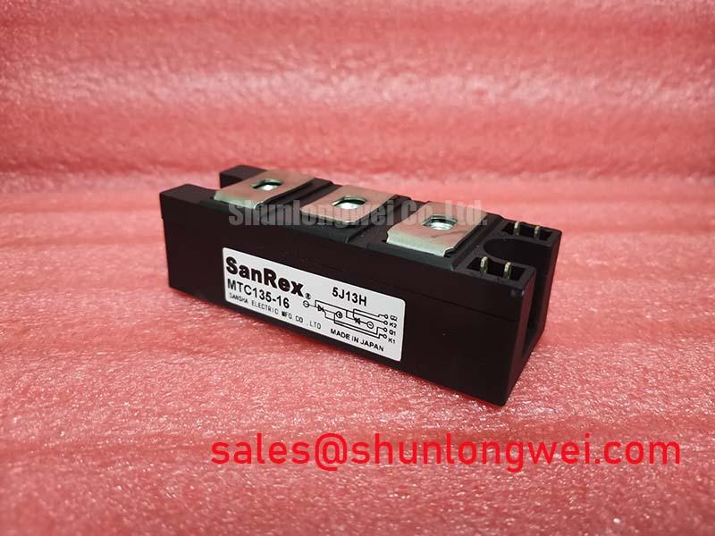
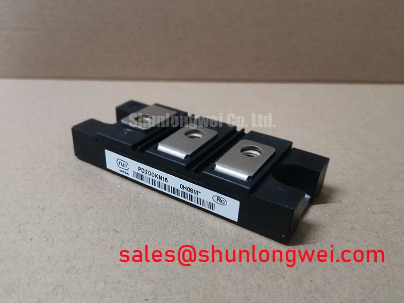
Because the available specification set does not confirm every dynamic and mechanical parameter, procurement and repair teams should match the PD200KN16 against the original equipment bill of materials, terminal arrangement, voltage class, current duty, cooling assembly, trigger circuit, and protection scheme. That verification is the appropriate basis for evaluating this SanRex isolated power module in a high voltage three phase motor solid state soft starter.