Content last revised on September 26, 2026
Field Diagnostics and Commissioning: Firing Angle Control in PE55FG120 Topologies
A firing angle adjustment changes the portion of an AC waveform delivered through a controlled rectifier. Before attributing an unexpected DC output to PE55FG120, trace the equipment schematic to establish whether this module occupies a controlled position and which external terminals serve the relevant circuit. The supplied product data does not establish its internal connection diagram, so terminal functions should be checked against the original module documentation rather than inferred from the product category.
During commissioning, record the controller command, measured AC input, DC output, and current waveform at comparable load conditions. In a phase controlled rectifier, delaying conduction generally reduces average DC output and can increase reactive power demand. The actual relationship depends on the bridge arrangement, supply impedance, load, and commutation behavior. An angle sweep from zero toward late firing should therefore be interpreted against the equipment’s documented operating range, not treated as a universal transfer curve for this module.
For a medium frequency induction melting or hardening furnace supply, this is a compatibility check rather than a claim that PE55FG120 was specified for that equipment. Compare the removed unit’s circuit diagram, terminal positions, mounting interface, and cooling arrangement with the proposed installation. 1200 V and 55 A are official ratings, but they cannot establish interchangeability on their own. When comparing another catalogued device such as PGH50N16, obtain its own circuit and mechanical documentation before assessing it as an alternative.
PE55FG120 Circuit Protection: Surge Current and Fuse Coordination
The 55 A official current rating should not be read as a short circuit or half cycle surge rating. A protection review needs the manufacturer’s specified surge current, its waveform and duration, the initial junction temperature, and the permitted repetition conditions. No ITSM value or test condition is established in the supplied product data, so a numeric surge margin cannot be assigned to PE55FG120.
For fuse coordination, compare the protective device’s clearing characteristics and let through energy with the applicable module limits under the same fault assumptions. A fuse selection based only on nominal operating current can overlook a fault that the module experiences before clearing. The original datasheet and the equipment protection study are needed before completing an I²t coordination table; neither a module I²t limit nor a mounting torque has been confirmed here.
After a suspected overcurrent event, isolate the assembly and compare its cold terminal measurements with the service documentation and, where available, a known good unit. Inspect the terminal joints and heatsink interface without assuming that an intact fuse proves the semiconductor is undamaged. Reapplication of reverse voltage also requires consideration of the documented thermal and recovery limits. Pro Tip: Verify the installed fuse’s clearing behavior against the module’s documented surge limits before relying on a successful no load restart.
Preventing Spurious Faults: AC Line Surges and Snubber Coordination
When an AC line disturbance coincides with a trip, capture the input and module terminal waveforms using appropriately rated measurement equipment. Separate a supply transient from normal commutation activity and controller noise before changing protection parts. The 1200 V official voltage rating is a device boundary, not an assertion that the assembled equipment meets surge immunity requirements.
As a Design Consideration, an MOV at the AC input and an RC snubber associated with a switching position can address different parts of the transient problem. MOV selection depends on the equipment’s continuous input voltage, expected surge exposure, upstream protection, and the voltage that reaches the module. Snubber selection depends on the measured commutation waveform, circuit arrangement, and component stresses. Neither value can be prescribed from the module’s voltage and current ratings alone. IEC 61000-4-5 is a reference for equipment surge testing; citing it does not imply that PE55FG120 or the finished system has passed a particular test.
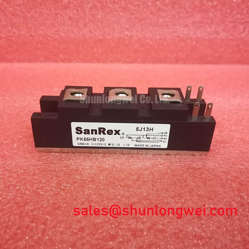
Check whether a companion position in the equipment schematic calls for a distinct module before ordering associated parts. PK55FG120 can be reviewed as a separate catalogued device in a rectifier assembly, but its role and compatibility must be established from its own connection diagram. For general context on gate drive, protection, and thermal integration, see IGBT Design & Integration; its IGBT guidance should not be substituted for thyristor gate specifications. SanRex power semiconductor resources likewise provide industry context, not manufacturer ratings for this Nihon Inter part.
PE55FG120 Operational Boundaries: Verifying Gate Trigger Behavior
If the equipment schematic confirms a gated thyristor position, compare the firing pulse measured at the installed device with the original controller and module specifications. Gate trigger current, pulse duration, permissible pulse rise, and any holding or repeated pulse requirement are not included in the confirmed PE55FG120 data. A proposed pulse rise threshold or back porch setting would therefore be an unsupported product claim.
Probe at the intended reference points and check whether a command reaches the gate while the appropriate main terminal voltage is present. A missing conduction interval may involve the controller, pulse transformer, wiring, load current, or device; one waveform alone does not identify the cause. As an Engineering Recommendation, keep the gate return path consistent with the documented circuit to reduce interference, then verify the firing waveform under the equipment’s actual operating conditions.
If the wider power supply also contains IGBT stages, evaluate their negative gate bias, Miller effect susceptibility, and any bootstrap supply separately. Those are system integration questions, not confirmed features of PE55FG120. Before energizing the repaired assembly, the engineer should resolve the module’s terminal map, mounting instructions, gate limits, and protection coordination from the original documentation, then confirm operation with controlled measurements.