

Content last revised on September 23, 2026
Benchtop Waveform Tuning: Mitigating Stress via Pulse Transformer Isolated Firing Circuit on PK55HB120
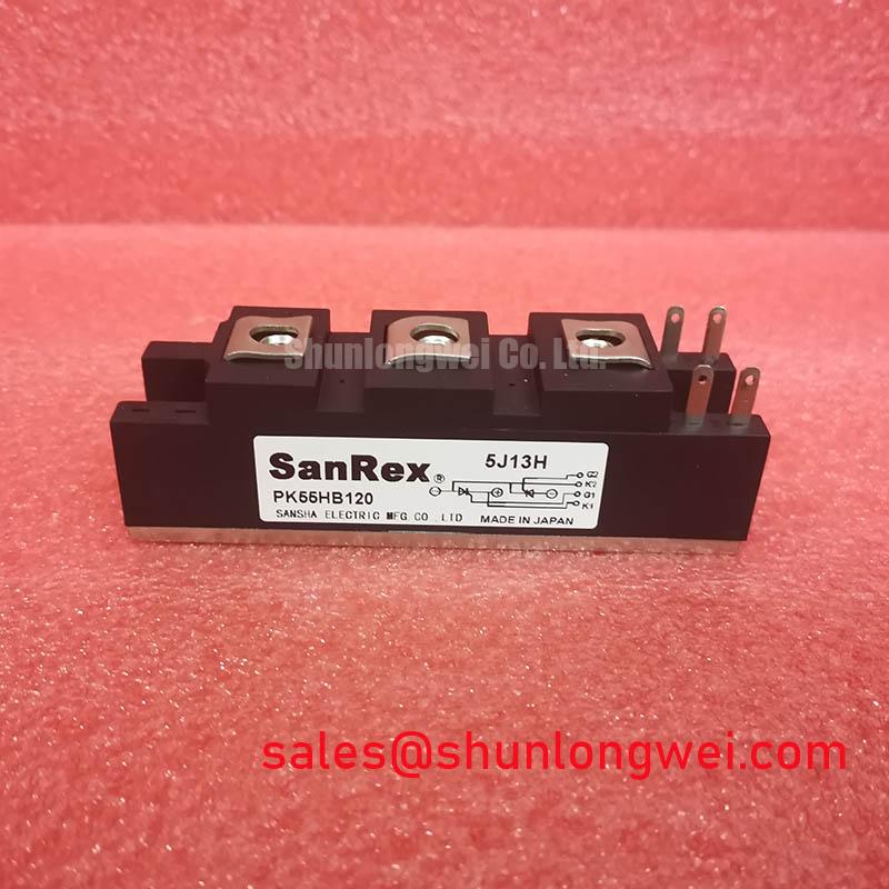
Begin the bench inspection by comparing the marked electrical boundaries with the replacement record: PK55HB120 is a SanRex Sansha Electric isolated power module with an official rated voltage of 1200.0 V and an official rated current of 55.0 A. Before connecting a firing circuit, confirm the terminal identification, isolation arrangement, and gate drive requirements against the original equipment documentation and the applicable SanRex technical literature. The product listing is available at PK55HB120.
A pulse transformer can provide galvanic separation between the control circuit and the power stage, but its pulse width, reset condition, secondary polarity, and wiring inductance remain system-level design matters. The supplied information does not establish a factory value for gate pulse rise time, gate current, holding current, multi-pulse timing, or a minimum gate resistance. These values should therefore be measured and tuned on the actual firing board rather than treated as fixed PK55HB120 specifications.
For a controlled bench test, observe the gate-to-cathode waveform with suitable isolation and confirm that the pulse reaches the intended terminal without excessive ringing. A suspected localized gate stress condition may also involve transformer saturation, incorrect polarity, insufficient pulse duration, or an unsuitable return path. Compare the firing signal with a known-good assembly and inspect the terminal connections before changing the pulse network. Any fuse coordination must use the device-specific forward-current and I²t data from the applicable manufacturer documentation; no fuse I²t value is specified in the supplied product data.
The SanRex Sansha Electric power semiconductor resource should be consulted for manufacturer-level documentation when the equipment drawing does not identify the required firing conditions. Engineers evaluating a related device can also review PK55FG120 as a separate, neutral comparison point, subject to full electrical and mechanical verification.
PK55HB120 Operational Boundaries: Evaluating AC Line Surge Immunity and Lightning Transient Limits
The 1200.0 V rating is an official device parameter, not a complete statement of allowable installation surge exposure. In a high-current green hydrogen electrolyzer DC power rectifier, the incoming AC network, transformer leakage, commutation behavior, bus capacitance, and protective coordination all influence the transient voltage seen by the module. The system designer should verify the peak repetitive and nonrepetitive voltage conditions using the complete rectifier schematic and measured switching waveforms.
AC input protection may include a coordinated combination of fuses, surge arresting components, and RC snubber networks. Selecting a metal oxide varistor requires checking its continuous operating voltage, energy capability, clamping behavior, fault mode, and coordination with the upstream protective device. The supplied PK55HB120 information does not specify a MOV part number, snubber capacitance, snubber resistance, lightning impulse withstand value, or compliance certification. These must be selected from the installation category, transformer arrangement, and applicable surge test requirements rather than inferred from the 1200.0 V rating.
IEC 61000-4-5 testing, where applicable to the equipment, evaluates the system port and protection arrangement; it does not establish that an individual thyristor or diode module independently passes an entire equipment EMC or surge-compliance assessment. During commissioning, capture the voltage at the module terminals and inspect the response during line switching, fault clearing, and controlled surge testing. Long motor or DC feeder cables can also create reflected-wave behavior, so cable routing and filtering should be assessed when the rectifier supplies a downstream converter or motor drive.
Place the auxiliary rectification stage and the main controlled rectifier within the same protection study. The PD104VT2T1 page may be useful for reviewing a related front-end or auxiliary-stage device, but it should not be treated as an automatic companion or substitute for the specified circuit position.
PK55HB120 Thermal-Electrical Optimization: Mechanical Mounting Torque Sequence and Practical Tuning
Inspect the isolated module base and heatsink interface before installation, removing contamination and checking that the mounting surfaces are flat, clean, and free from burrs. The official product data supplied for this page identifies the package as an Isolated Power Module, but it does not provide a verified mounting torque, baseplate dimension, thermal resistance value, thermal impedance curve, or approved thermal interface material thickness. Those values must be taken from the relevant mechanical drawing or manufacturer datasheet before production assembly.
Thermal interface material should be applied as a controlled, uniform layer appropriate to the actual surface finish. Excess compound can obstruct mechanical seating, while insufficient coverage can leave local air gaps. Tighten the mounting hardware in a gradual, alternating sequence so that contact pressure develops evenly across the base. The final torque, fastener grade, washer arrangement, and any insulation requirements remain system and manufacturer documentation items, not official PK55HB120 parameters supplied here.
After installation, check the electrical terminals for correct conductor placement and secure clamping. A loose power connection can create local heating and waveform distortion, while an over-tightened connection can damage the terminal structure. Record the initial no-load and loaded temperature behavior, then compare phase or channel temperatures under the same operating condition. A rising temperature trend may require investigation of heatsink airflow, interface aging, current imbalance, switching timing, or terminal resistance.
⚠️ Maintenance Note: During preventive maintenance, monitor contact temperature and clean the heatsink and airflow path while checking the assembly for moisture or condensation before energizing the equipment.
For electrolyzer rectifier cabinets, enclosure humidity, cold-start condensation, dust accumulation, and fan performance deserve the same attention as semiconductor ratings. The 55.0 A official current rating should be evaluated with the actual duty cycle, waveform, cooling arrangement, ambient temperature, and protection system. It should not be converted into a universal continuous-current guarantee for every cabinet configuration.
Benchtop Waveform Tuning: Mitigating Stress via Thermal and Electrical Margins during High Peak Operation on PK55HB120
Before any high-current test, confirm that the test fixture includes the specified fuse, current limiting, emergency isolation, and correctly rated measurement equipment. The official data supplied here confirms 1200.0 V, 55.0 A, and the isolated module construction, but it does not provide a sinusoidal 10 ms half-cycle surge rating, ITSM, junction-temperature limit, thermal impedance, repetitive surge duty, or reverse-voltage recovery limit. These missing values must be verified in the manufacturer’s applicable datasheet before a surge test is authorized.
A controlled rectifier test should monitor line current, module terminal voltage, firing timing, heatsink temperature, and the recovery interval before reverse voltage is reapplied. Abnormal current sharing or an unexpected voltage spike may result from gate timing, circuit impedance, transformer behavior, snubber selection, commutation overlap, or measurement error. Inspect the complete waveform rather than assigning a single cause from one symptom.
Fuse selection requires coordination with the module’s documented surge and I²t limits. A fast semiconductor fuse can reduce fault energy, but its suitability depends on prospective short-circuit current, clearing time, installation impedance, and the rectifier’s operating cycle. If the relevant fuse coordination table is unavailable, the equipment should not be described as protected to a specific short-circuit level.
For long-term service evaluation, document the thermal rise after stabilized loading, inspect the heatsink contact after thermal cycling, and repeat terminal checks during scheduled shutdowns. The Power Semiconductor Selection Guide provides broader selection context for voltage, current, protection, cooling, and verification decisions without replacing the PK55HB120 manufacturer documentation.