

Content last revised on September 19, 2026
Transient Dynamics & Electrical Design: Dynamic Firing Delay Angle Adjustment on PKA2232PI
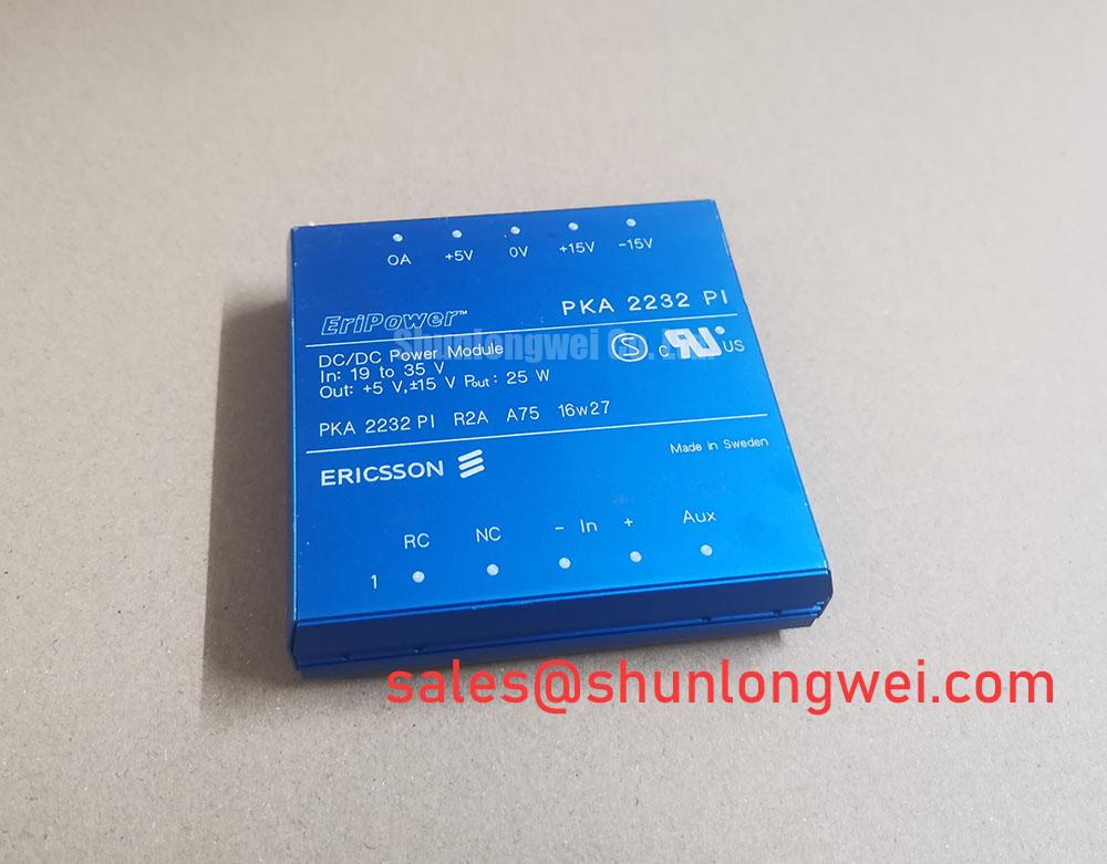
With the equipment isolated and discharged, first verify that the installed module marking reads PKA2232PI, then compare its wiring positions and heat-sink contact face with the original assembly documentation before releasing any terminal hardware.
The available official product data identifies the PKA2232PI as a SanRex (Sansha Electric) power module with a 5.0 A rated current and a Standard Industrial Rating working-voltage designation. The published information supplied for this product does not define its thyristor and diode arrangement, repetitive voltage limit, surge-current rating, reverse-recovery values, terminal diagram, fuse coordination data, mounting torque, or thermal resistance. These items must be confirmed from the original equipment documentation or the applicable SanRex technical documentation before commissioning.
| Product attribute | Declared value | Classification |
|---|---|---|
| Model | PKA2232PI | Official product identification |
| Manufacturer | SanRex (Sansha Electric) | Official product identification |
| Rated current | 5.0 A | Official Specification |
| Working voltage | Standard Industrial Rating | Official Specification as supplied |
| Package | SanRex Power Module | Official Specification |
In a three phase motor solid state soft starter, firing delay angle adjustment determines how much of each AC waveform is delivered to the motor during acceleration. Before evaluating the PKA2232PI in such equipment, maintenance personnel should establish whether the module is installed in the phase-control path, a rectified auxiliary supply, or another power section. The module designation alone does not establish the circuit topology, so terminal functions must be traced from the original schematic rather than inferred from the package.
For phase-controlled operation, increasing the firing delay generally reduces delivered motor voltage while increasing waveform distortion and reactive power demand. The practical concern during commissioning is not selecting a universal firing angle, but confirming that the controller delivers balanced trigger timing across the power paths and that the resulting current remains within the module’s 5.0 A rated current. Oscilloscope measurements should be referenced to an approved measurement scheme suitable for the equipment’s voltage class.
Engineering Recommendation: inspect control wiring for loose screening, damaged insulation, moisture ingress, and routing that allows power-conductor noise to couple into firing signals. Common-mode ground movement can alter an apparent trigger command at the module terminals, especially where long motor cables, contactor coils, or braking hardware share enclosure space. The system engineer should verify trigger timing at the actual module connection points while the equipment is operated under controlled conditions.
Fuse selection must not be based solely on the 5.0 A current rating. Proper coordination depends on the semiconductor’s published surge capability and the fuse manufacturer’s time-current and I²t data, neither of which is included in the available PKA2232PI data. Do not transfer an I²t table from another module family. For replacement evaluation, the physical format, circuit function, voltage class, thermal path, and protection documentation should all be checked. The linked FRS200CA100 page can be reviewed as a separate power-module reference, but it should not be treated as an automatic replacement for PKA2232PI without a complete electrical and mechanical comparison.
⚠️ Maintenance Note: Periodically monitor terminal contact temperature and confirm that cooling-air passages remain clear before returning the starter to sustained service.
PKA2232PI Operational Boundaries: Evaluating Reverse Recovery Charge Limits
Reverse recovery behavior matters when a diode path changes from conduction to blocking during commutation. Peak reverse-recovery current, recovery duration, and recovery softness influence switching stress, ringing, and conducted or radiated noise. No official PKA2232PI values for reverse-recovery charge, peak recovery current, or recovery time are included in the supplied product information. It would therefore be inaccurate to assign a recovery classification or predict switching loss for this exact module.
Design Consideration: where the surrounding circuit contains commutating diodes, inspect waveform behavior with a correctly rated differential-voltage probe and a current-measurement method appropriate to the test location. A sharp current reversal or persistent ringing may indicate that the commutation network, cable routing, supply impedance, or suppression parts need review. It does not by itself identify a single defective component.
DC-link capacitor condition also affects transient behavior. Capacitor ESR contributes to voltage ripple and heat generation when ripple current flows, as explained in the external technical reference on capacitor equivalent series resistance and ripple current. This is a circuit-level consideration, not an official PKA2232PI characteristic. Inspect capacitor venting, mounting security, and measured ripple behavior in accordance with the machine manufacturer’s maintenance procedure.
Where the soft starter uses magnetic current measurement, signal integrity should be checked from sensor output through the controller input rather than judged from a displayed current value alone. The operating principle of GMR and related magnetoresistive sensing illustrates why sensor position, external fields, and signal conditioning require system-level validation. The PKA2232PI product data does not state that such a sensor is integrated within the module.
PKA2232PI Operational Boundaries: Saturable Reactor and Snubber Sizing Limits
RC snubbers and saturable reactors are determined by measured circuit energy, commutation behavior, insulation coordination, and the allowable limits stated in the complete system documentation. The supplied PKA2232PI information does not publish dv/dt capability, di/dt capability, gate sensitivity, or snubber component values. No module-specific resistor, capacitor, or reactor value can therefore be specified from the available official data.
Engineering Recommendation: keep high-current commutation paths compact, maintain secure terminal contact, and route low-level control wiring away from rapidly changing power nodes where practical. These measures help reduce parasitic coupling that can produce unwanted trigger behavior or overvoltage ringing. After any wiring, capacitor, or suppression-network intervention, system engineers should verify peak voltage and current waveforms against the original equipment limits during controlled switching tests.
Long motor cables can produce reflected-wave stress at the motor terminals. This is primarily a cable-and-system issue that should be assessed at the motor and starter output using the equipment manufacturer’s approved test conditions. If the cabinet includes regenerative braking, braking choppers, or high-power braking resistors, their energy handling and switching sequence must be evaluated separately. The available PKA2232PI data does not establish that this module controls those functions.
Negative gate bias, gate-drive dead time, and parallel IGBT current-sharing practices should also not be attributed to PKA2232PI unless the original circuit documentation identifies an IGBT gate-drive stage connected to this module. If a separate IGBT subsystem is present, its driver design, dead-time control, and return-path screening require independent verification. For broader maintenance and test context in industrial power conversion, consult Industrial Applications.
Assembly Integrity & Layout Architecture: Evaluating Post-Surge Reverse-Voltage Blocking for PKA2232PI
Before reapplying reverse voltage after a surge event, isolate the equipment, discharge stored energy through the approved procedure, and inspect the module mounting interface, terminals, busbar alignment, fuse holders, suppression parts, and nearby capacitor connections. A surge can affect several elements in the commutation path, so a module-focused visual inspection should be followed by circuit-level testing against a known-good schematic or service record.
The requested 10 ms half-cycle surge value, commonly associated with non-repetitive sinusoidal surge testing, is not supplied for PKA2232PI in the available official data. It is therefore not appropriate to calculate a junction-temperature margin, determine post-surge blocking capability, or state a permissible surge current for this model. Obtain the applicable manufacturer documentation before using the module in a design or repair decision that depends on surge survival.
Design Consideration: thermal reliability depends on stable heat transfer as well as electrical loading. During scheduled shutdowns, remove accumulated dust from the heat sink and airflow route, inspect for dried or disturbed thermal interface material, and check for condensation evidence around terminals and insulation surfaces. Mounting torque and terminal torque must follow the original equipment documentation because no PKA2232PI-specific torque value is included in the supplied product data.
After reassembly, verify that busbars sit without mechanical preload, that terminal hardware is secure, and that control connectors are fully seated before applying a controlled low-risk functional test. If abnormal voltage waveform shape, uneven phase behavior, unexpected heating, or repeated protection trips are observed, stop the test and compare the measured circuit behavior with the original soft-starter documentation before returning the equipment to service.